8
english
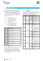
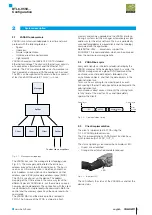
The BTL6-V55V... Micropulse transducer implements the
EUROMAP 75 suggestion. The device evaluates the
communication with the manager via data objects. These
data objects are mapped in the VARAN client’s memory
address space. The data object address table, Tab. 4-1,
contains essential information about the PDO and SDO
mapping and is mapped at the beginning of the client’s
MAS.
PDO
prozess data objects
RPDO receive process data objects
RSDO
receive service data objects
SDO
service data objects
TPDO
transmit process data objects
TSDO
transmit service data objects
Byte No.
Description
0
Start address of RPDO
1
2
Length of RPDO
3
4
Start address of TPDO
5
6
Length of TPDO
7
8
Start address of RSDO
9
10
Length of RSDO
11
12
Start address of TSDO
13
14
Length of TSDO
15
Tab. 4-1: Data object address
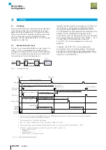
The transmitting and receiving operations are seen from
the viewing point of the client. E.g. the RPDO is the
process data object received by the client.
The message counter in the header of the data object
mappings is used to keep data consistency. It is
incremented when new data is available in the related data
object.
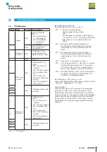
4.1
RPDO mapping
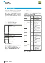
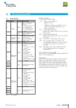
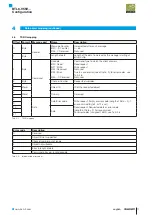
The “Number of channels” sets the number of the active
measurement channels. The maximum number of available
channels of the device can be obtained from the 0x61E0
“AI_Number_Of_Channels” message.
Offset Name
Format Description
0
Header
Byte
Bit 0…5 message
counter
1
Byte
RPDO mapping ID:
always = 0
2
Number of
channels
Byte
Number of measuring
channels to be
measured, possible
values: 1 or 2
3
Byte
always 0
4
Measuring
channel 1
Word
AI control word-2 for
channel 1
– Bit 3: Channel reset
– Bit 4: ADC enabled
(Starts or stops data
update)
– Bit 9: Set simulation
operating mode
(should be 0)
5
6
Byte
AI selected
measurement range for
channel 1, always 1
7
Byte
AI sensor type for
channel 1, always 0x58
(Stroke)
8
Measuring
channel 2
Word
AI control word-2 for
channel 2
– Bit 3: Channel reset
– Bit 4: ADC enabled
(Starts or stops data
update)
– Bit 9: Set simulation
operating mode
(should be 0)
9
10
Byte
AI selected
measurement range for
channel 2, always 1
11
Byte
AI sensor type for
channel 2, always 0x58
(Stroke)
Tab. 4-2: RPDO mapping
4
Data object mapping
BTL6-V55V…
Configuration
Summary of Contents for BTL6-V55 Series
Page 1: ...BTL6 V55 Konfigurationshandbuch deutsch...
Page 2: ...www balluff com...
Page 15: ...BTL6 V55 Configuration Manual english...
Page 16: ...www balluff com...

