www.balluff.com
5
english
2.1
VARAN fundamentals
VARAN is manufacturer-independent, real-time network
protocol with the following features:
– Speed
– Openness
– Simple implementation
– Optimised real-time performance
– High reliability
VARAN is based on the IEEE 802.3 100TX standard
Ethernet technology. The physical Ethernet layer consists
of a connector, a transformer and the Ethernet PHY
module. The PHY module provides an auto-crossover so
that crossed and uncrossed CAT5e cables can be used.
The BTL can be supplied with power via the bus cable, if
at least one AWG26 cable (0.14 mm
2
) is in use.
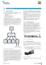
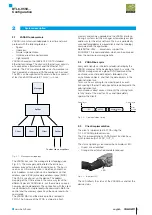
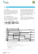
Fig. 2-1:
Manager
Splitter
Client
Client
To other clients or splitters
Client
Splitter
Manager/client topology
The VARAN bus uses the manager/client topology (see
Fig. 2-1). The manager administrates the entire bus
address area with up to 65,280 participants. The bus is
seen as a 4 GB memory area, in which each client has
64 kb address space which can be handled as control
address space (CAS) or memory address space (MAS).
The CAS is used to set up the device. The address
mapping of the CAS is done in the same way for all the
different types of VARAN clients, but the memory space is,
however, device-dependent. The connection with the client
is established with simple read/write commands. Both the
control and the memory space have their own read/write
commands.
The VARAN MAC and the device profile is realised in
FPGA. The firmware of the FPGA is stored in a flash
memory and can be upgraded via the VARAN interface.
During a system start the manager automatically assigns
addresses for the entire network. The bus is periodically
scanned for added or removed clients and the topology
compared with the application.
Balluff BTL6-V55V-… transducers support the
EUROMAP 75 recommendation, which can be obtained
from the www.euromap.org website.
2.2
VARAN bus cycle
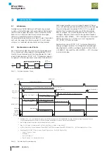
Every data transfer is initiated and administrated by the
VARAN manager. At the beginning of each bus cycle, the
VARAN manager sends a global SYNC command, the
isochronous real-time data objects followed by the
asynchronous objects, and then the data objects in the
administration task.
Tasks such as scanning for new participants or even
transporting Ethernet IP data packets are performed in the
administration task.
Asynchronous direct access interrupts the running tasks
(at any time) at the most for 25 μs and immediately
updates the clients.
Fig. 2-2:
ASYNC
ISO
DA
Task
Administration
Global Sync
Global Sync
Next
period
t
Communication timing
2.3
Client implementation
The client is implemented in FPGA using the
0.1.4.2 VARAN protocol version.
The PLL implementation’s VARAN client function has a
synchronous output, SYNC_OUT_0.
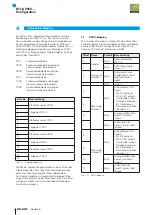
The status signalling is realised with one bicolour LED:
– Green: link established
– Orange: link established and data received
Fig. 2-3: Bicolour LED
The LED reflects the status of the VARAN bus and not the
device status.
LED
2
System description
BTL6-V55V…
Configuration
Summary of Contents for BTL6-V55 Series
Page 1: ...BTL6 V55 Konfigurationshandbuch deutsch...
Page 2: ...www balluff com...
Page 15: ...BTL6 V55 Configuration Manual english...
Page 16: ...www balluff com...

