BIW1-A/C/E/G310-M_ _ _ _-P1-S115
Micropulse Linear Transducer in Profile Housing
english
4
4
Wiring
Note the following when mak-
ing electrical connections:
System and control cabi-
net must be at the same
ground potential.
To ensure the electromagnetic
compatibility (EMC) which Balluff
warrants with the CE Mark, the
following instructions must be
strictly followed.
BIW transducer and the proces-
sor/control must be connected
using shielded cable.
Shielding: Copper filament
braided, 85% coverage.
The shield must be tied to the
connector housing in the BKS
connector (
➥
➥
➥
➥
➥
Fig. 4-3); see in-
structions accompanying the con-
nector.
The cable shield must be
grounded on the control side, i.e.,
connected to the protection
ground.
Pin assignments can be found in
➥
➥
➥
➥
➥
Table 4-1. Connections on the
controller side may vary according
to the controller and configuration
used.
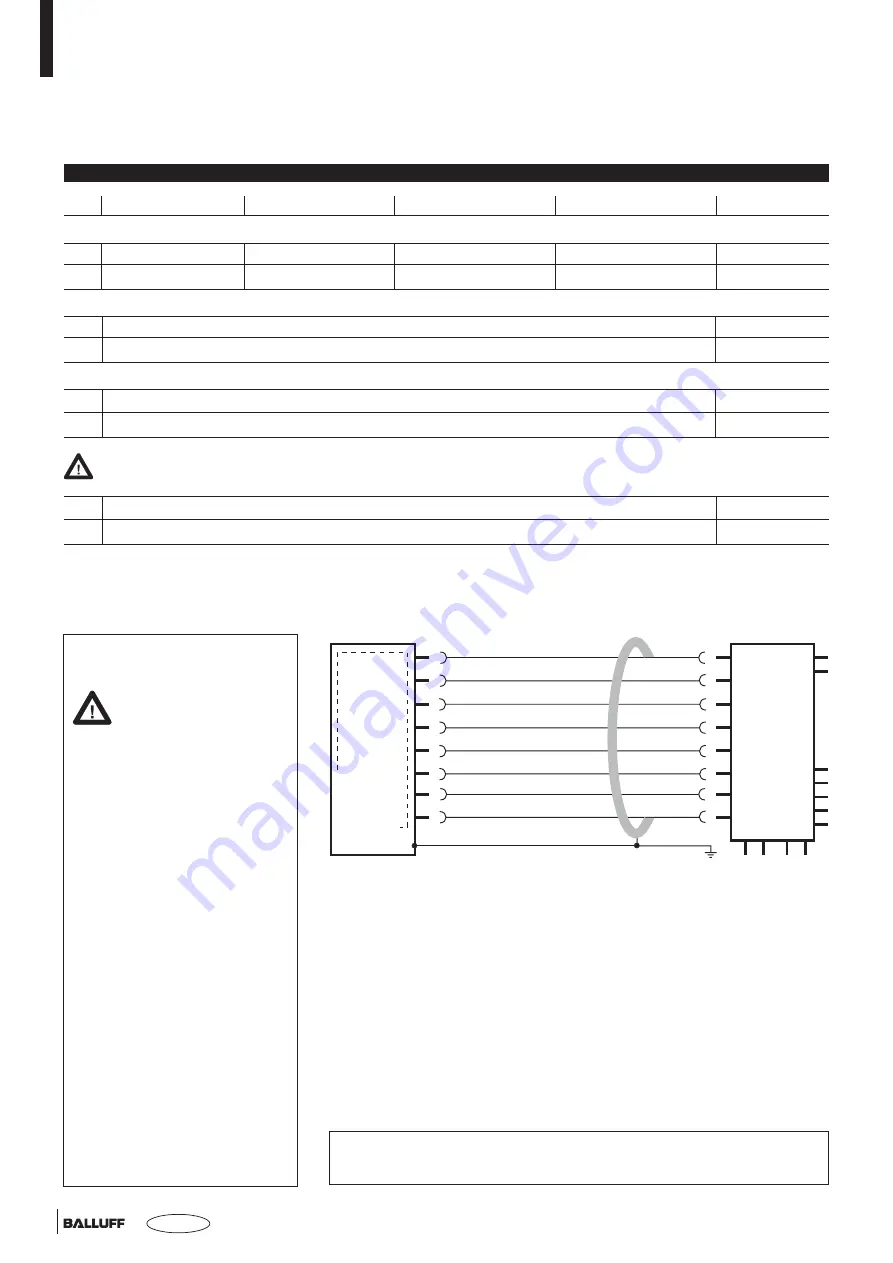
BIW1-A310...S115
YE
GY
PK
RD
GN
BU
BN
WH
Output slope -
0 V
Reserved
Output slope +
0...10 V
GND
+24 V DC
Reserved
Controller
1
2
3
4
5
6
7
8
Fig. 4-1: BIW1-A310-M...S115 with controller and BKS-S115-PU05,
Connection example
Table 4-1: Wiring assignment
Output slope
To have the output voltage rise starting at the zero point, jumper Pin 4 and
Pin 1.
To have the output voltage fall starting at the zero point, leave Pin 4
unconnected.
Once the slope has been selected and applied and the slope selection
connections removed, reselecting programs the BIW again with the other
slope. This means the slope select connection must remain in place so
that it stays the same even after the unit is powered off multiple times.
Pin
BIW1-A310...
BIW1-C310...
BIW1-E310...
BIW1-G310...
Cable BKS
Output signal:
2
0 V
0 V
0 V
0 V
GY gray
5
0...10 V
0...20 mA
4...20 mA
-10...+10 V
GN green
Supply voltage:
6
GND
BU blue
7
+24 V DC
BN brown
Output slope:
1
Output slope -
YE yellow
4
Output slope +
RD red
Reserved leads must remain unconnected.
3
Reserved
PK pink
8
Reserved
WH white
Note:
The slope selection is not applied until the unit is reset or powered
off/on.


