EN
L-L 234.00-BM
26 / 40
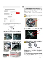
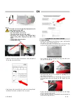
• Insert the burner and fix it to the plate by tightening the nut
supplied onto the screw G;
• Locate the black cable with 7-pin Wieland plug running out of the
electrical panel and insert the plug into the socket H on the
burner;
• Remove the burner cover and adjust the air pressure switch to the
value listed in the technical specifications table of the user
manual;
• Adjust the gas pressure switch to 75% of its supply pressure
• Air pressure switch setting: 2 mbar
• Gas pressure switch setting: 75 % P
IN
• Close the burner cover;
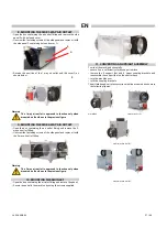
• Open the box containing the gas valve group and remove the valve
already secured onto a support plate
• Secure the gas valve group to the machine using the M8 and M5
screws.
• Connect the stainless steel hose to the burner, taking care to
properly insert the N gas seal:
• Locate the cable with 6-pin Wieland plug running out of the gas
valve group and insert the plug into the burner socket;
• Apply one of the two stickers with the serial number on the
nameplate of the machine characteristic data:
• Apply the second sticker with the serial number on the Assembly
and Installation Declaration contained in the user manual:
• The burner is not pre-adjusted by the manufacturer and must be
set according to data reported in Table of Technical
Characteristics of the user manual: follow the instructions in the
manual to complete the connection of the machine to the gas
supply system and for commissioning
Warning
Check all threaded connections on the gas line.
When commissioning, check for any gas leaks or
seepages using soap and water
7. MOUNTING THE 1-WAY AIR OUTLET
• Open the box containing the air outlet fitting and remove the
panel;
• Secure the panel to the machine by using the 4xM6 screws
G
H
N

