background image


ES


L-L 234.00-BM 

29 / 40 


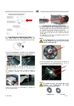
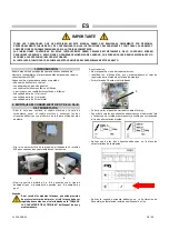
3. MONTAJE DE LA CAJA DE TERMOSTATOS 

• Abrir la caja que contiene el cuadro eléctrico y la caja de 

termostatos y sacar la caja de termostatos. 


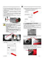
•  Insertar con atención la barra con las sondas de los termostatos 

en el correspondiente agujero presente en la máquina: el bastidor 

interno perforado actúa como guía para la correcta colocación de 

los bulbos de los termostatos. 


• Fijar la caja de termostatos en la máquina, utilizando los 2 

tornillos M5 que ya están atornillados en la máquina. 

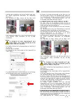
• Conectar el enchufe negro a la respectiva toma presente en el 

cuadro eléctrico y fijar el cable en el correspondiente muelle 

fijacable. 


•  Conectar la toma y el enchufe del conector C1 para la conexión 

eléctrica del motor. 


4. MONTAJE DEL GRUPO MOTOR-VENTILADOR 

• Abrir la caja que contiene el grupo motor-ventilador, sacar este 

último y conservar las dos etiquetas adhesivas con el número de 

lote para usarlas más adelante. 

• Desmontar de la máquina el panel de soporte del ventilador, 

extrayendo los 8 tornillos M5, y conservar los tornillos para 

utilizarlos al volver a montar el panel. 

•  Disponer el panel de soporte sobre un plano de apoyo robusto y 

colocar sobre el mismo el grupo motor-ventilador. 


Atención 

Situar el grupo motor-ventilador de manera tal que el 

agujero de descarga D esté siempre en posición vertical 

inferior, en dirección del suelo.


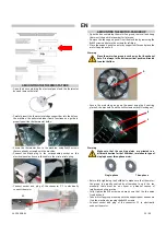
•  Fijar el grupo motor-ventilador en el panel utilizando las 4 placas 

de centrado E, los soportes de fijación F y los 4 tornillos M con 

tuerca autoblocante. 


Atención 

En el caso del modelo 145, las placas de centrado deben 

orientarse de manera diferente según si el motor es 

monofásico o trifásico: 


 Monofásico 

Trifásico 


D

F

E

Summary of Contents for FARM 110

Page 1: ...O MANUEL D ASSEMBLAGE MONTAGEANLEITUNG ASSEMBLY MANUAL MANUAL DE ENSAMBLAJE GENERATORE D ARIA CALDA GENERATEUR D AIR CHAUD WARMLUFTERZEUGER SPACE HEATER GENERADOR DE AIRE CALIENTE FARM 85 FARM 110 FAR...

Page 2: ...TTSSTUTZEN AIR INLET RACOR DE ENTRADA AIRE 5 GRUPPO VALVOLA GAS GROUPE SOUPAPE GAZ GASVENTILGRUPPE GAS VALVE GROUP GRUPO V LVULA DE GAS 6 BRUCIATORE A GAS BRULEUR A GAZ GASBRENNER GAS BURNER QUEMADOR...

Page 3: ...ITTSSTUTZEN AIR INLET RACOR DE ENTRADA AIRE 5 GRUPPO VALVOLA GAS GROUPE SOUPAPE GAZ GASVENTILGRUPPE GAS VALVE GROUP GRUPO V LVULA DE GAS 6 BRUCIATORE A GAS BRULEUR A GAZ GASBRENNER GAS BURNER QUEMADOR...

Page 4: ...ERMOSTATI Aprire la scatola contenente il quadro elettrico e la scatola termostati prelevare il quadro elettrico e conservare le due etichette adesive con numero di lotto per l uso successivo Fissare...

Page 5: ...la scatola contenente il gruppo motore ventilatore prelevare il gruppo motore ventilatore e conservare le due etichette adesive con numero di lotto per l uso successivo Smontare dalla macchina il pann...

Page 6: ...orsettiera Applicare una delle due etichette adesive con numero di lotto sulla targhetta dati caratteristici della macchina Applicare la seconda etichetta adesiva con numero di lotto sulla Dichiarazio...

Page 7: ...raccordi della pompa gasolio gi predisposti Prelevare il filtro gasolio con staffa e fissare la staffa sulla parete della macchina con le viti M5 Prelevare il nipplo e dopo aver ricoperto la parte fil...

Page 8: ...bile in acciaio inossidabile al bruciatore avendo cura di inserire correttamente la guarnizione N per gas Individuare il cavo con spina Wieland 6 poli uscente dal gruppo valvola gas ed inserire la spi...

Page 9: ...re il raccordo uscita aria 2 vie Svitare le viti di fissaggio del pannello laterale e sostituirlo con il raccordo uscita aria 2 vie Attenzione Il raccordo uscita aria 2 via laterale approvato per il f...

Page 10: ...DU BO TIER DES THERMOSTATS Ouvrir la bo te contenant le coffret lectrique et le bo tier des thermostats sortir le coffret lectrique et conserver les deux tiquettes adh sives portant le num ro de lot...

Page 11: ...R VENTILATEUR Ouvrir la bo te contenant le groupe moteur ventilateur sortir ce groupe et conserver les deux tiquettes adh sives portant le num ro de lot qui seront utilis es ult rieurement Sur la mach...

Page 12: ...refermer le boitier des bornes Appliquer une des deux tiquettes adh sives portant le num ro de lot sur la plaquette des caract ristiques de la machine Appliquer la deuxi me tiquette adh sive portant...

Page 13: ...accords quipant la pompe fuel Prendre le filtre fuel muni de l trier et fixer ce dernier sur le b ti de la machine l aide des vis M5 Prendre l embout et apr s avoir envelopp de t flon la partie filet...

Page 14: ...eur en ayant soin d introduire correctement le joint N pour gaz Rep rer le c ble avec fiche Wieland 6 p les sortant du groupe soupape gaz et introduire la fiche dans la prise pr vue sur le br leur App...

Page 15: ...raccord de sortie d air et extraire le raccord 2 voies D visser les vis de fixation du panneau lat ral et le remplacer par le raccord de sortie d air 2 voies Attention Le raccord de sortir d air 2 vo...

Page 16: ...DES SCHALTKASTENS UND DES THERMOSTATKASTENS Den Karton ffnen der den Schaltkasten und den Thermostatkasten enth lt Den Schaltkasten herausnehmen und die zwei Klebeetiketten mit der Losnummer f r den s...

Page 17: ...Karton ffnen der das Ventilatoraggregat enth lt Das Ventilatoraggregat herausnehmen und die zwei Klebeetiketten mit der Losnummer f r den sp teren Gebrauch beiseite legen Vom Ger t die Tr gerplatte d...

Page 18: ...gen ausrichten ohne die Kabelposition zu ver ndern Muttern und Unterlegscheiben erneut anbauen und festziehen Anschlussleistenkasten wieder schlie en Ein Klebeetikett mit der Losnummer auf das Typensc...

Page 19: ...d Stecker ist Den Stecker in die hierf r vorgesehene Steckbuchse H am Brenner einstecken Den Brennerdeckel abnehmen und die zwei flexiblen Schl uche an den bereits vorger steten Anschl ssen der Heiz l...

Page 20: ...e Gasventilgruppe unter Verwendung der Schrauben M8 und M5 am Ger t befestigen Den flexiblen Schlauch aus rostfreiem Stahl an den Brenner anschlie en Hierbei darauf achten dass die Gasdichtung N ordnu...

Page 21: ...uftaustrittsstutzen enth lt und den 2 Wege Luftaustrittsstutzen herausnehmen Das Seitenpaneel durch L sen der Befestigungsschrauben abbauen und durch den 2 Wege Luftaustrittsstutzen ersetzen Achtung D...

Page 22: ...E ELECTRICAL PANEL AND THERMOSTAT BOX Open the box containing the electrical panel and the thermostat box remove the electrical panel and keep the two stickers with lot number for later use Secure the...

Page 23: ...e screws for refitting Place the support panel on a sturdy support surface and place the motor fan group onto it Warning Place the motor fan group in such a way that the exhaust hole D is always in th...

Page 24: ...er manual 5 MOUNTING THE DIESEL BURNER 5 1 RIELLO BURNER Open the box containing the diesel burner remove it and keep the two stickers with lot number for later use Consult the user manual of the burn...

Page 25: ...place Remove the diesel filter and its bracket and secure the bracket to machine wall using M5 screws Remove the nipple and after wrapping the threaded portion to be inserted into the filter with Tef...

Page 26: ...ng care to properly insert the N gas seal Locate the cable with 6 pin Wieland plug running out of the gas valve group and insert the plug into the burner socket Apply one of the two stickers with the...

Page 27: ...astening screws of the side panel and replace it with the 2 way air outlet fitting Warning The 2 way air outlet is approved to function only when mounted on the side as in the previous figure 10 MOUNT...

Page 28: ...EL CTRICO Y DE LA CAJA DE TERMOSTATOS Abrir la caja que contiene el cuadro el ctrico y la caja de termostatos sacar el cuadro el ctrico y conservar las dos etiquetas adhesivas con el n mero de lote p...

Page 29: ...DEL GRUPO MOTOR VENTILADOR Abrir la caja que contiene el grupo motor ventilador sacar este ltimo y conservar las dos etiquetas adhesivas con el n mero de lote para usarlas m s adelante Desmontar de l...

Reviews: