background image

BVRD Series Microphones

Installation Instructions

BVRD Series Microphones issue 5

19

Summary of Contents for BVRD series

Page 1: ...BVRD Series Microphones Installation Instructions Firmware version BVRDMIC V1 09 Manual name BVRD Series Microphones Issue 5 ECR 2785 Date of issue Nov 2013...

Page 2: ...co uk Website http www baldwinboxall co uk This equipment has been designed and manufactured to conform to the following EC Standards EMC EN55103 1 Environment Classification E1 EMC EN55103 2 Environ...

Page 3: ...____6 Colour Code for Processor Bypass switch 6 Recommended Cable Types _____________________________6 Firmware Configuration Introduction_________________________________________7 BVRD USB Config Sof...

Page 4: ...ncy Mode Keyswitch Turned 45 ______________ 15 To make an All Call Emergency Live Announcement 15 To make an Emergency Announcement to Selected Zones 15 To Play a DVA Message to All Zones 16 To Cancel...

Page 5: ...this manual without the prior permission of Baldwin Boxall Communications Limited In the interest of continual product development Baldwin Boxall Communications Limited reserves the right to make cha...

Page 6: ...rnings Cautions and Notes Warnings describe potential threats to health or life e g Cautions describe potential threats to the equipment e g Notes are statements that are useful to the user in the con...

Page 7: ...f features suitable for any installation Figure 1 1 Typical BVRD8 Microphone The Microphones are configured during commissioning via an internal USB port and communicate with the main control system v...

Page 8: ...as a Paging microphone with emergency options disabled and as a Fire microphone only when the keyswitch is turned 50 x 30mm LCD Displays showing zone names status Speak Now indicator to show the user...

Page 9: ...280mA Max Serial Data Link See note below RS485 Type 0 Protocol 9600 Baud 8 bit Even Parity 1 Stop Bit Dimensions W x H x D BVRD8 205mm x 48mm x 177mm BVRD16 275mm x 48mm x 177mm BVRD24 345mm x 48mm...

Page 10: ...BVRD Series Microphones Installation Instructions 4 BVRD Series Microphones issue 5...

Page 11: ...onnection which is usually terminated to a local wall mounted BMS8 Termination box Figure 2 1 Typical BMS8 Termination Box CAUTION The BMS8 Termination Box has a standard RJ45 socket to allow use of a...

Page 12: ...phones should be terminated to 2 x 4 core Fire Rated cable MICC FP200 or similar It is strongly recommended that separate cables be used for the audio pair to eliminate potential interference from the...

Page 13: ...ific options such as communication protocols naming the inputs and outputs DVA message selection and setting up button allocation To access the USB socket on the BVRD Microphone remove the two screws...

Page 14: ...Page from BVRD USB Configuration Software 3 3 LOADING DEFAULT VALUES To load the default configuration settings the following procedure should be used 1 Remove the RJ45 lead 2 Turn the keyswitch 45 t...

Page 15: ...and the latched faults should be cleared Variable Default Setting I D or Input Physical Input 2 RS485 Protocol Type 0 RS485 Baud Rate 9600 Selection Latch Off Stop Bit 1 Data Bits 8 Parity Even Surv...

Page 16: ...ys do not show the correct or any zone information then perform the following procedure Thisforcesarescantodetectthecorrectnumberofzonebuttons 1 Turn the Emergency Mode Keyswitch 45 and press and hold...

Page 17: ...LCD Displays G Voice Alarm Active Indicator B Zone Select Buttons H Message Status LCD Display C Function Buttons F1 F5 I Message Selection Buttons D Emergency Mode Keyswitch J Message Navigation But...

Page 18: ...e what is currently being broadcast by the zone and also if any faults are present on that zone This allows the operator to easily determine the current status of the system Figure 4 2 Typical Zone LC...

Page 19: ...1 Select the required zones using the Zone Select Buttons Item B in Figure 4 1 The zone status displays will show Selected for the relevant zones 2 Press the SPEAK button Item L in Figure 4 1 and wai...

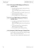
Page 20: ...ess the SPEAK button to confirm the selection 4 3 4 To Cancel BGM Background Music to selected zones 1 Select the required zones using the Zone Select Buttons Item B in Figure 4 1 The zone status disp...

Page 21: ...splays will show Selected for the relevant zones 2 Press the SPEAK button Item L in Figure 4 1 and wait for the SPEAK NOW Indicator to illuminate The zone status displays will show the BVRD microphone...

Page 22: ...to All Zones 1 Press the Zone Selection buttonconfigured for Select All or press every Zone Selection Button Item B in Figure 4 1 or press the relevant Function Button Item C in Figure 4 1 2 Press th...

Page 23: ...on should be taken as soon as possible to correct faults as they impair the correct operation of the system 4 5 2 BVRD Series Microphones Fault Indicators The BVRD Series Microphones include three fau...

Page 24: ......

Page 25: ...BVRD Series Microphones Installation Instructions BVRD Series Microphones issue 5 19...

Page 26: ...BVRD Series Microphones Installation Instructions 20 BVRD Series Microphones issue 5...

Reviews: