


Getting Started
MN1258V4 08/2000
59
The configuration editor will syntax highlight all Mint keywords as they are typed. The correct
syntax for the firmware being used can be uploaded from the controller by selecting the ‘Load
Syntax’ option from the ‘Edit’ menu.
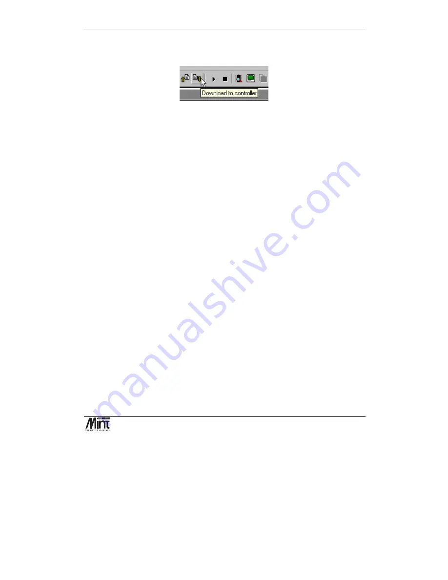
Figure 4-23: Download Button
In order to execute the configuration file in the editor window it must be downloaded to the
controller by pressing the ‘download’ button.
Once the program has been downloaded to the controller it can be executed by either typing
RUN
at
the Mint command line or pressing the ‘play’ button.
Whenever a Mint program is
RUN
, the Configuration Buffer is executed first followed by the
Program Buffer. The Configuration or Program Buffer can be executed individually by typing:
RUN CON
(for the
Configuration Buffer
)
or
RUN PROG
(for the
Program Buffer
)
The following list of parameters is normally set-up in the Configuration Buffer:
•
Servo loop gains
- to tune the system response.
•
Scale factor
- to set the units of measure of the application.
•
Maximum following error
- to set a safe maximum difference between actual and desired
positions.
•
Default speeds accelerations and decelerations for the system
- to determine the shape
of the trapezoidal velocity profile.
•
Error features such as hardware and software limits, stop inputs and error input.
The parameters in the Configuration Buffer are generally to be set-up only once for an application,
but can at any time be altered in the Program Buffer.
The Mint Configuration Tool provides a graphical method for setting common parameters that
would be placed in a configuration file. Having completed the Start Up Wizard, the Mint
Configuration Tool can be started in wizard or manual modes. The wizard mode steps through each
of the configuration screens for each axis selected during the Start Up Wizard.
Digital Inputs
Each of the digital input channels may be configured to be level (active high or low) or edge
triggered (positive, negative or both edges). Digital inputs may also be assigned to axes for use as
limit switch inputs etc.
Summary of Contents for NextMove BX
Page 1: ...MN1258V4 08 2000 NextMove BX Installation Manual for Mint v4 Issue 4 0...
Page 2: ...NextMove BX Installation Manual for Mint v4 ii MN1258V4 08 2000...
Page 4: ...NextMove BX Installation Manual for Mint v4 iv MN1258V4 08 2000...
Page 8: ...NextMove BX Installation Manual for Mint v4 viii MN1258V4 08 2000...
Page 12: ...NextMove BX Installation Manual for Mint v4 xii MN1258V4 08 2000...
Page 18: ...NextMove BX Installation Manual for Mint v4 6 MN1258V4 08 2000...
Page 22: ...NextMove BX Installation Manual for Mint v4 10 MN1258V4 08 2000 Figure 3 3 Board Settings...
Page 46: ...NextMove BX Installation Manual for Mint v4 34 MN1258V4 08 2000...
Page 78: ...NextMove BX Installation Manual 66 MN1258V4 08 2000...
Page 82: ...NextMove BX Installation Manual 70 MN1258V4 08 2000...
Page 88: ...NextMove BX Installation Manual 76 MN1258V4 08 2000...
Page 92: ...NextMove BX Installation Manual 80 MN1258V4 08 2000...
Page 94: ...NextMove BX Installation Manual 82 MN1258V4 08 2000...


