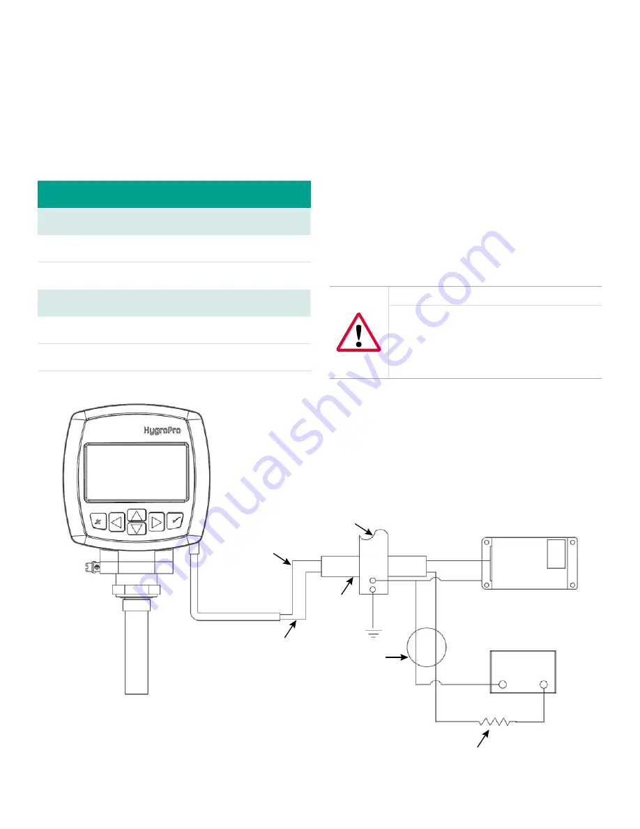
Bus bar
Brown
Blue
Red
3
4
1
2
+24V
24V return
–
+
OCB(*)
Green
Black
Black
IS ground
R1, 250 ohms, ±5%, 1/4 Watt
MTL706
Power supply
4 - 20 mA
Analog input device
Figure 6: Hazardous area connections
1.4.2d Requirements for external devices
When connecting the
HygroPro
to external devices, the
allowable total load capacitance and inductance for
those devices are listed in the manufacturer’s datasheets.
The entity parameters of the external devices (e.g. voltage,
current and power) must be equal to or lower than the
same specifications for the
HygroPro
.
The entity parameters for the
HygroPro
are listed in
Table 5 below.
Table 5: HygroPro entity parameters
Loop power supply
U
i
= 28 V
P
i
= 0.653 W
L
i
= 62 µH
I
i
= 93.3 mA
C
i
= 0
RS485 digital output
U
i
= 3.72 V
P
i
= 212 mW
L
i
= 62 µH
I
i
= 228 mA
C
i
= 67 µF at 5.36 V
1.4.2e Special conditions for safe operation
The “X” at the end of the
HygroPro
ATEX certificate number,
Bas06ATEX0019X
, indicates that special conditions are
required for safe operation in Europe. These conditions are:
1. The equipment must be protected against impact or
friction with ferrous metals.
2. The bare ends of the connecting cable must be
terminated in such a way that the terminations are
afforded a degree of protection of not less than IP20
ingress protection.
3. The
HygroPro
is incapable of withstanding the
500 VAC test between all inputs and frame for one
minute. Therefore, the
HygroPro
must be earthed by
connecting the outer grounding screw on the
HygroPro
with the equipotential bonding system. Follow the
local standards and electrical codes regarding the
equipotential bonding system.
WARNING!
Never connect or disconnect the HygroPro in
the hazardous area when supply power or the
communication circuit is energized. Isolate
the supply lines in the non-hazardous area
first.
Following the same special conditions listed above is
recommended for regions outside of Europe as well.
8


