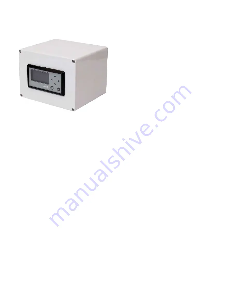
2.3.4 Wall mount
The wall mount
dew.IQ
consists of a panel mount unit pre-installed in a standard Type 4X, IP66 wall mount enclosure. See
Figure 39 on page 96, Figure 40 on page 97 and Figure 41 on page 98 for dimensions and installation notes.
The enclosure should be mounted on a vertical surface that provides adequate clearance for proper operation and
configuration by completing the following steps:
1. Loosen the four (4) screws on the front of the enclosure, pull the door straight forward until it stops and then swing the
door open (it is hinged on the left side ).
2. Install four (4) self-drilling wall anchors in your mounting location per the hole pattern shown in Figure 39 on page 96.
3. Mount the enclosure on the wall using four (4) #8 x 1-1/2” machine screws in the four mounting holes provided.
4. Prior to operation, the door must be closed and secured with the four screws located at the corners.
14
Summary of Contents for Panametrics dew.IQ
Page 1: ...dew IQ Moisture analyzer User s manual 910 295 Rev C...
Page 2: ...ii...
Page 3: ...dew iQ Moisture analyzer User s manual 910 295 Rev C October 2017 i...
Page 4: ...no content intended for this page ii...
Page 63: ...no content intended for this page 56...
Page 101: ...no content intended for this page 94...
Page 103: ...Figure 39 Wall Mount Outline and Installation ref dwg 712 1823 1 of 3 96...
Page 104: ...Figure 40 Wall Mount Outline Installation ref dwg 712 1823 2 of 3 97...
Page 105: ...Figure 41 Wall Mount Outline Installation ref dwg 712 1823 3 of 3 98...
Page 106: ...Figure 42 Rack Mount Outline Installation ref dwg 712 1824 99...
Page 107: ...Figure 43 Panel Mount Outline Installation ref dwg 712 1825 100...
Page 108: ...Figure 44 Bench Top Outline Installation ref dwg 712 1826 101...
Page 109: ...Figure 45 Interconnection Diagram ref dwg 702 1381 102...
Page 111: ...FIgure 46 Main Menu Map Using M Series Probe 104...
Page 112: ...FIgure 47 Main Menu Map Using IQ probe 105...
Page 113: ...no content intended for this page 106...


