background image

Copyright 2005 Baker Hughes Company.

Deutsch–DPI880 Bedienungsanleitung | 25

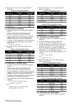
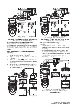
Abbildung


8: Beispielkonfiguration: Simulieren der 

Temperatur oder des Widerstands

2.8  Thermoelement-Anschlüsse (TC)

Schließen Sie die Anschlussleitungen des 

Thermoelements an den entsprechenden Thermoelement-

Minianschluss an (Abbildung


9). Der breitere Kontakt ist 

der negative. Verbinden Sie dann den Anschluss mit dem 

Gerät.

2.8.1  Messen/Simulieren eines Thermoelements

Verfahren:
1. Schließen Sie das Gerät an (Abbildung


9) und ändern 

Sie ggf. die Option Konfig. (Tabelle


1).

2. Wählen Sie den Modus aus dem Menü zur Moduswahl 

(Tabelle


2).

3. Wählen Sie Einstellg. (



), um den Betriebsmodus 

von Temperatur auf mV oder von mV auf Temperatur 

umzustellen.

4. Ändern Sie ggf. die Werte unter Einstellg. (Tabelle


4 & 

Tabelle


5) und/oder die simulierten Messgrößen für 

das System (Tabelle


7).

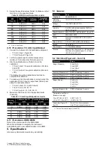
Abbildung


9: Beispielkonfiguration: 

Messen/Simulieren der Temperatur (°C/°F) oder der 

mV-Werte eines Thermoelements

2.9  Transmitterkalibrierung

Verfahren:
1. Schließen Sie das Gerät an (Abbildung


10 

Abbildung


11) und ändern Sie ggf. die Option Konfig. 

(Tabelle


1).

2. Wählen Sie die gewünschte Kalibrierung aus dem 

Menü zur Moduswahl (Tabelle


2 & Tabelle


3) und 

ändern Sie ggf. die Werte unter Einstellg. (Tabelle


4 & 

Tabelle


5).

3. Legen Sie die Ausgangswerte an das System an 

(Tabelle


7).

Abbildung


10: Beispielkonfiguration: 

Transmitterkalibrierung mit externer 2-Leiter-

Speisespannung

TC

mA +

3W

 MAX

 30V

COM

V

Hz

mA -

4W

RTD

-

+

,

, ,

100

0

MENU

OK

HOLD

ESC

1
2

mA

MENU

OK

0.00

850°C

Pt100

MENU

OK

0.0

4000

:

4W

3W 2W

2W

+VE

-VE

+

-

-

1

1

Einstellg.

a) RTD °C oder °F

E2KPȍ

Edit

Einstellg.

Edit

mV

MENU

OK

HOLD

ESC

1
2

MENU

OK

34.7

1372°C

K

MENU

OK

0.373

CJ=25.4

75mV

1

TC

mA +

3W

 MAX

 30V

COM

V

Hz

mA -

4W

RTD

Einstellg.

a) °C oder °F (Eingang)

b) mV (Eingang)

°C

K

Einstellg.

Einstellg.

mV

MENU

OK

HOLD

ESC

1
2

MENU

OK

MENU

OK

1

TC

mA +

3W

 MAX

 30V

COM

V

Hz

mA -

4W

RTD

,

, ,

100

0

-

+

+VE

-VE

+

-

34.7

1372°C

K

0.373

CJ=25.4

75mV

c) °C oder °F (Ausgang)

d) mV (Ausgang)

Einstellg.

Edit

Einstellg.

Edit

Einstellg.

30V MAX

Vin

24Vo

mA

-mA (24Vo)+

TC

mA +

3W

 MAX

 30V

COM

V

Hz

mA -

4W

RTD

MENU

OK

0.083

55mA

MENU

OK

HOLD

ESC

1
2

-

+

+VE

-VE

,

, ,

100

0

2

5.0V

40.400

50kHz

1

-

+

Edit

Einstellg.

Maximum: 30 V

Summary of Contents for Druck DPI 880

Page 1: ...Druck com DPI880 Multi function Calibrator Instruction Manual English 1 16 Deutsch 17 34 Espa ol 35 52 Fran ais 53 70 Italiano 71 88 Portugu s 89 106 107 126 127 142 143 162 mA 24Vo...

Page 2: ......

Page 3: ...nstruction Manual i A1 A2 A3 MENU OK HOLD ESC 1 10 9 TC mA 3W MAX 30V COM V Hz mA 4W RTD 8 7 6 5 4 3 2 A2 A3 11 12 3xLR6 AA B1 30V MAX Vin 24Vo mA mA 24Vo 13 14 15 1 2 Sk2 Sk1 553 2 K 1372 C CJ 0 0 13...

Page 4: ...Copyright 2005 Baker Hughes Company ii DPI880 Instruction Manual English B1...

Page 5: ...al Pressure Module UPM The DPI880 includes these functions Measure mA Volts mV Hz pulse count Supply mA Volts mV Hz pulse count Measure simulate i Resistance Temperature Detector RTD or C F ii thermoc...

Page 6: ...his initiative https druck com weee Item Description 1 On or off button 2 Left hand soft key Selects the function above it on the display Item 24 Example Edit 3 Moves back one menu level Leaves a menu...

Page 7: ...sition flashes on off a button or task selection is set in area or Sets the Dual Function area selections to off This saves the battery power Refer to Table 2 Table 3 Help Shows a connection diagram f...

Page 8: ...RTD resistance or TC Simulate thermocouple temperature OR mV Table 3 Menu Options Task Selections Area Options If applicable Description White button A Dual Function is set Black button Dual Function...

Page 9: ...value for the Nudge output Example 1 000 mA increments Additional data Select Settings To select and set up values for the Span Check output Example output cycle This cycle repeats automatically Addit...

Page 10: ...from the task selection menu Table 2 Table 3 Note Use the Dual Function area to do two operations at the same time If the area selection is not necessary set this area to off This saves the battery p...

Page 11: ...ect the task from the task selection menu Table 2 3 If necessary adjust the Settings Table 4 Table 5 and or the output values to the system Table 7 Figure 6 Example Configuration To Measure Supply Hz...

Page 12: ...Thermocouple TC Connections Attach the TC wires to the applicable TC mini connector Figure 9 The wider blade is the negative Then attach the connector to the instrument 2 8 1 Measure Simulate a Thermo...

Page 13: ...in the top right hand corner 3 Supply the output values to the system Table 7 i Example Nudge output a Use Edit to set a value less than the switch value b Use the buttons to change the value in smal...

Page 14: ...k rate in the applicable units minute To measure pressure with another operation Figure 14 use the same procedure Figure 14 Example Configuration To Measure Pressure and Temperature 2 12 Error Indicat...

Page 15: ...bration is correct select the applicable mA input task Table 2 and apply these values mA 55 40 24 18 12 6 0 open circuit Then mA 0 6 12 18 24 40 55 Table 8 Calibration Equipment Function Calibration E...

Page 16: ...nt get to a stable temperature minimum 5 minutes since the last power on 3 Use the calibration menu Table 9 to do a two point calibration Zero and FS The display shows the applicable instructions to c...

Page 17: ...calibrate each range 3 To make sure that the calibration is correct select the applicable ohms input task Table 2 4 Make a 4 wire connection to the applicable standard resistor Table 18 and measure th...

Page 18: ...100 0 50 to 3 0 0 004 0 06 200 0 50 to 3 0 0 005 0 06 300 0 50 to 3 0 0 007 0 07 400 0 50 to 3 0 0 008 0 07 1000 0 05 to 0 8 0 015 0 30 2000 0 05 to 0 4 0 026 0 40 4000 0 05 to 0 3 0 049 0 80 Table 2...

Page 19: ...200 to 400 C 0 36 F 0 20 C D 100 392 JIS 1604 1989 328 to 1 202 F 200 to 650 C 0 45 F 0 25 C Ni 100 DIN 43760 76 to 482 F 60 to 250 C 0 36 F 0 20 C Ni 120 MINCO 7 120 112 to 500 F 80 to 260 C 0 36 F...

Page 20: ...0 to 100 C 3 4 F 1 9 C S IEC 584 212 to 3214 F 100 to 1768 C 2 5 F 1 4 C E IEC 584 454 to 238 F 270 to 150 C 1 6 F 0 9 C E IEC 584 238 to 1796 F 150 to 980 C 0 7 F 0 4 C N IEC 584 454 to 4 F 270 to 2...

Page 21: ...ulse Messen Simulieren i Widerstandsthermometer RTD oder C F ii Thermoelement TC mV oder C F iii Widerstand Kaltstellen Kompensation CJ Automatisch Manuell Schritt Rampenfunktionen Automatisch Manuell...

Page 22: ...verwendung und zum Recycling von Wertstoffen ben tigen wenden Sie sich bitte an Ihr zust ndiges Abfallentsorgungsunternehmen vor Ort Klicken Sie auf den folgenden Link um Hinweise zur R cknahme unsere...

Page 23: ...m sie zu w hlen Beispiel nach links nach rechts 25 Men zur Moduswahl Pro Bereich und ist eine Moduswahl zul ssig Cursorposition blinkt In Bereich oder ist eine Tasten oder Moduswahl eingestellt Deakti...

Page 24: ...RTD Messen der RTD Temperatur Messen des Widerstands oder des Werts des RTD TC Messen der Temperatur ODER des mV Werts des Thermoelements Nur wenn ein UMM in IDOS Technologie angeschlossen ist Es han...

Page 25: ...s anzuwendenden RTD Typs Pt50 Pt100 TC Typ w hlen nur TC Auswahl eines anwendbaren Thermoelementtyps K J T Trigger Pegel nur Hz Einstellen der Amplitude bei der das Ger t ein Frequenzsignal misst Stan...

Page 26: ...und Konfiguration des Ausgangs Defin Schritt Beispielhafter Ausgangszyklus Auto Wiederholg Optional Weitere Daten Tabelle 6 W hlen Sie Einstellg Auswahl und Konfiguration des Ausgangs Rampe Beispielh...

Page 27: ...is Mithilfe des Bereichs der Dualfunktion k nnen Sie zwei Vorg nge gleichzeitig ausf hren Wenn keine Auswahl in Bereich erforderlich ist deaktivieren Sie diesen Bereich Auf diese Weise werden die Batt...

Page 28: ...s dem Men zur Moduswahl Tabelle 2 3 ndern Sie ggf die Werte unter Einstellg Tabelle 4 Tabelle 5 und oder die simulierten Messgr en f r das System Tabelle 7 Abbildung 7 Beispielkonfiguration Messen der...

Page 29: ...kalibrierung Verfahren 1 Schlie en Sie das Ger t an Abbildung 10 Abbildung 11 und ndern Sie ggf die Option Konfig Tabelle 1 2 W hlen Sie die gew nschte Kalibrierung aus dem Men zur Moduswahl Tabelle 2...

Page 30: ...t Im Display werden die zum ffnen und Schlie en des Schalters anzuwendenden Werte angezeigt 5 Falls Sie den Test wiederholen m chten dr cken Sie die Taste ESC um die Werte zur ckzusetzen Abbildung 12...

Page 31: ...rlichen Arbeiten Anforderungen f r die R ckverfolgbarkeit der Kalibrierung Betriebsbedingungen 3 2 Reinigen des Ger ts Reinigen Sie das Geh use mit einem feuchten flusenfreien Tuch und einem milden Re...

Page 32: ...n 4 W hlen Sie zur berpr fung der Kalibrierung den zutreffenden mA Ausgangsmodus Tabelle 2 und legen Sie folgende Ausgangswerte an mA 0 1 4 12 20 24 CJ Standard RTD Messf hler Spezifikation 50 mK f r...

Page 33: ...Stellen Sie sicher dass die Abweichung den vorgegebenen Grenzwerten entspricht Tabelle 14 oder Tabelle 15 4 6 Verfahren Frequenz Eingang Ausgang 1 Schlie en Sie das Ger t an die Kalibrierausr stung a...

Page 34: ...henden Ohm Eingangsmodus Tabelle 2 4 Stellen Sie einen 4 Leiter Anschluss zu dem entsprechenden Standardwiderstand her Tabelle 18 und messen Sie den Wert Abbildung 7 5 Stellen Sie sicher dass die Abwe...

Page 35: ...tion Kalibrator abweichung Zul ssige DPI880 Abweichung 0 0 50 bis 3 0 0 003 0 05 100 0 50 bis 3 0 0 004 0 06 200 0 50 bis 3 0 0 005 0 06 300 0 50 bis 3 0 0 007 0 07 400 0 50 bis 3 0 0 008 0 07 1000 0...

Page 36: ...0 20 C D 100 392 JIS 1604 1989 328 bis 1 202 F 200 bis 650 C 0 45 F 0 25 C Ni 100 DIN 43760 76 bis 482 F 60 bis 250 C 0 36 F 0 20 C Ni 120 MINCO 7 120 112 bis 500 F 80 bis 260 C 0 36 F 0 20 C Bereich...

Page 37: ...F 1 9 C S IEC 584 212 bis 3214 F 100 bis 1768 C 2 5 F 1 4 C E IEC 584 454 bis 238 F 270 bis 150 C 1 6 F 0 9 C E IEC 584 238 bis 1796 F 150 bis 980 C 0 7 F 0 4 C N IEC 584 454 bis 4 F 270 bis 20 C 1 8...

Page 38: ...Copyright 2005 Baker Hughes Company 34 DPI880 Bedienungsanleitung Deutsch...

Page 39: ...los de medici n universales UMM Ejemplo El m dulo de presi n universal UPM El calibrador DPI880 incluye las siguientes funciones Medici n de mA voltios mV Hz contador de pulsos Alimentaci n de mA volt...

Page 40: ...n contacto con la administraci n de residuos local o regional Visite el siguiente enlace para obtener instrucciones de recuperaci n y m s informaci n sobre esta iniciativa https druck com weee Element...

Page 41: ...funci n Ejemplo Ir a la izquierda Ir a la derecha 25 Men de selecci n de tareas Se permite una selecci n de tareas en cada rea y Posici n del cursor encendido y apagado del parpadeo Se ha ajustado un...

Page 42: ...20 mV Hz Medici n de la frecuencia unidades Tabla 4 RTD Medici n de la temperatura de RTD Medici n de la resistencia de RTD o TC Medici n de la temperatura del termopar O mV S lo si est conectado un I...

Page 43: ...Tipo TC s lo TC Seleccionar un tipo de termopar aplicable K J T Nivel de disparo S lo Hz Ajustar la amplitud en la que el instrumento detecta una se al de frecuencia Valor predeterminado 5 V Detec Au...

Page 44: ...ida Repet autom tica Opcional Datos adicionales Tabla 6 Seleccione Ajustes Seleccionar y configurar valores para la salida Rampa Ejemplo de ciclo de salida Repet autom tica Opcional Datos adicionales...

Page 45: ...2 Seleccione la tarea en el men de selecci n de tareas Tabla 2 y Tabla 3 Nota Utilice el rea de funci n dual para realizar dos operaciones al mismo tiempo Si no es necesaria la selecci n del rea desa...

Page 46: ...te la opci n Configurar Tabla 1 2 Seleccione la tarea en el men de selecci n de tareas Tabla 2 3 Si es necesario defina los Ajustes Tabla 4 y Tabla 5 y o los valores de salida para el sistema Tabla 7...

Page 47: ...brar un transmisor 1 Conecte el instrumento Figura 10 y Figura 11 y si es necesario ajuste la opci n Configurar Tabla 1 2 Seleccione la tarea de calibraci n aplicable en el men de selecci n de tareas...

Page 48: ...opuesta hasta que el interruptor cambie de condici n de nuevo La pantalla muestra los valores aplicables de apertura y cierre del interruptor 5 Si desea repetir la prueba pulse ESC para reiniciar los...

Page 49: ...Producto p ej DPI880 N mero de serie Descripci n de la aver a trabajo que se debe realizar Requisitos de trazabilidad de la calibraci n Condiciones de funcionamiento 3 2 Limpieza de la unidad Limpie...

Page 50: ...ciones apropiadas para terminar la calibraci n CJ Sonda RTD est ndar Precisi n 50 mK para 23 a 82 4 F 5 a 28 C Term metro digital Precisi n 10 mK Ohmios de RTD Resistencia est ndar de 0 a Resistencia...

Page 51: ...les a la calibraci n mV 0 30 60 90 120 O bien Voltios V 0 3 6 9 12 6 Aseg rese de que el error est dentro de los limites especificados Tabla 14 o Tabla 15 4 6 Procedimientos Entrada salida de Hz 1 Con...

Page 52: ...mios aplicable Tabla 2 4 Realice una conexi n de 4 cables a la resistencia est ndar aplicable Tabla 18 y mida el valor Figura 7 5 Aseg rese de que el error se encuentra en los limites especificados Ta...

Page 53: ...DPI880 permitido 0 0 50 a 3 0 0 003 0 05 100 0 50 a 3 0 0 004 0 06 200 0 50 a 3 0 0 005 0 06 300 0 50 a 3 0 0 007 0 07 400 0 50 a 3 0 0 008 0 07 1000 0 05 a 0 8 0 015 0 30 2000 0 05 a 0 4 0 026 0 40...

Page 54: ...000 385 IEC 751 328 a 752 F 200 a 400 C 0 36 F 0 20 C D 100 392 JIS 1604 1989 328 a 1 202 F 200 a 650 C 0 45 F 0 25 C Ni 100 DIN 43760 76 a 482 F 60 a 250 C 0 36 F 0 20 C Ni 120 MINCO 7 120 112 a 500...

Page 55: ...32 a 212 F 0 a 100 C 3 4 F 1 9 C S IEC 584 212 a 3214 F 100 a 1768 C 2 5 F 1 4 C E IEC 584 454 a 238 F 270 a 150 C 1 6 F 0 9 C E IEC 584 238 a 1796 F 150 a 980 C 0 7 F 0 4 C N IEC 584 454 a 4 F 270 a...

Page 56: ...Copyright 2005 Baker Hughes Company 52 Manual de instrucciones DPI880 Espa ol...

Page 57: ...ple le module de pression universel UPM Le DPI880 comporte les fonctions suivantes Mesure en mA volts mV Hz impulsions Alimentation en mA volts mV Hz impulsions Mesure simulation i un capteur de temp...

Page 58: ...te la r utilisation et les dispositifs de recyclage veuillez contacter les services locaux ou r gionaux de r cup ration des d chets concern s Consultez le site ci dessous pour obtenir des instructions...

Page 59: ...r es applicables aux t ches s lectionn es dans l l ment 25 zones et plage et unit s de mesure 24 Sk1 2 Fonction de touche programmable Pour s lectionner une fonction disponible appuyez sur la touche p...

Page 60: ...el date d talonnage num ro de s rie informations IDOS 1 Menu de s lection des t ches 2 3 4 5 Tableau 2 Tableau 3 T che sortie en mA Menu de s lection des t ches 6 Affichage sortie en mA Tableau 2 Tabl...

Page 61: ...nsation SF n cessaire Manuelle Mesure la temp rature SF et r gle la valeur applicable L instrument utilise cette valeur pour appliquer la compensation SF n cessaire type S lectionner type RTD RTD uniq...

Page 62: ...ermet de s lectionner et de configurer des valeurs pour la sortie Pas fixes Exemple de cycle de sortie R p ter Auto en option Donn es suppl mentaires Tableau 6 s lectionnez Param tres Permet de s lect...

Page 63: ...cordez l instrument Figure 4 et Figure 5 et si n cessaire r glez le menu Config Tableau 1 2 S lectionnez la t che dans le menu de s lection de t ches Tableau 2 et Tableau 3 Remarque utilisez la zone F...

Page 64: ...ents 2 3 et 4 fils d un RTD ou d une r sistance 2 7 1 Mesure simulation de RTD ou ohms Pour mesurer simuler des valeurs RTD ou ohms 1 Raccordez l instrument Figure 7 et Figure 8 et si n cessaire r gle...

Page 65: ...les param tres Tableau 4 et Tableau 5 et ou les valeurs de sortie vers le syst me Tableau 7 Figure 9 Exemple de configuration mesure simulation de la temp rature C F ou des valeurs en mV d un TC 2 9...

Page 66: ...les boutons pour modifier la valeur par petits incr ments ii Exemple sortie Rampe a D finissez des valeurs Haut et Bas applicables la valeur du contact Tableau 6 Puis pour obtenir une valeur de contac...

Page 67: ...re 14 Exemple de configuration mesure de la pression et de la temp rature 2 12 Messages d erreur Si l affichage indique ou Assurez vous que la plage est correcte Assurez vous que tous les quipements e...

Page 68: ...ie en mA Tableau 10 et Tableau 11 Pr cision mA Fonction Dual Tableau 10 mV OU TC mV talonneur en mV Pr cision entr e sortie en mV Tableau 12 et Tableau 14 Pr cision TC mV Tableau 20 Volts OU Volts Dua...

Page 69: ...ge d erreur est comprise dans les limites sp cifi es Tableau 12 ou Tableau 13 4 5 Proc dures sortie en mV volts 1 Raccordez l instrument l quipement d talonnage Figure 4 2 Attendez que l quipement att...

Page 70: ...e menu d talonnage Tableau 9 pour r aliser un talonnage deux points pour chaque plage Plage 0 399 9 a R sistance nominale z ro Effectuez un branchement 4 fils vers la r sistance 0 Figure 7 b R sistanc...

Page 71: ...C mV talonnage deux points z ro et PE L cran affiche les instructions n cessaires pour effectuer l talonnage 4 Pour vous assurer que l talonnage est correct s lectionnez la t che d entr e ou la t che...

Page 72: ...n 10 10 C 30 50 C 0 003 PE C 14 50 F 86 122 F 0 0017 PE F Connecteurs Figure A1 l ment 10 Quatre connecteurs femelles de 4 mm Une prise de mini connecteur TC Param tre Valeur Plage mesure 0 55 mA 0 30...

Page 73: ...minute pph impulsions heure Pr cision 0 999 99 Hz 0 003 de la valeur 0 0023 Hz 0 50 000 kHz 0 003 de la valeur 0 0336 Hz ppm 0 59 999 0 003 de la valeur 0 138 cpm pph 0 99 999 0 003 de la valeur 0 5...

Page 74: ...EC 584 32 212 F 0 100 C 3 4 F 1 9 C S IEC 584 212 3214 F 100 1768 C 2 5 F 1 4 C E IEC 584 454 238 F 270 150 C 1 6 F 0 9 C E IEC 584 238 1796 F 150 980 C 0 7 F 0 4 C N IEC 584 454 4 F 270 20 C 1 8 F 1...

Page 75: ...MM Esempio il Modulo di pressione universale UPM Gli apparecchi DPI880 dispongono delle seguenti funzioni Misurazione mA Volt mV contatore Hz impulsi Alimentazione mA Volt mV contatore Hz impulsi Misu...

Page 76: ...i di raccolta riutilizzo e riciclaggio contattare gli enti locali che si occupano di smaltimento dei rifiuti Visitare il seguente sito per le istruzioni relative alle procedure di recupero e per maggi...

Page 77: ...ione possibile selezionare solo un operazione per ogni area e posizione del cursore lampeggia acceso spento impostata un operazione o selezionato un tasto nell area o Imposta la Duplice Funzione disat...

Page 78: ...5 mA V Misura 30 V mV Misura 120 mV Hz Misura la frequenza unit di misura Tabella 4 RTD Misura la temperatura da una sonda RTD Misura la resistenza RTD o TC Misura della temperatura o mV di una termoc...

Page 79: ...onare un tipo di RTD adeguato Pt50 Pt100 Selez T C TC soltanto Per selezionare un tipo di termocoppia adeguato K J T Livello trigger Hz soltanto Per impostare l ampiezza alla quale lo strumento rileva...

Page 80: ...i Per selezionare ed impostare un valore per l emissione Passo fisso Esempio ciclo emissione Ripetizione opzionale Dati aggiuntivi Tabella 6 selezionare Imposta Per selezionare ed impostare un valore...

Page 81: ...a alla Duplice Funzione per eseguire due operazioni contemporaneamente Se la selezione dell area non necessaria disabilitare l area In questo modo si minimizza il consumo di energia della batteria 3 S...

Page 82: ...p Tabella 1 2 Selezionare l operazione dal menu operazioni Tabella 2 3 Se necessario modificare Imposta Tabella 4 e Tabella 5 e o i valori di uscita al sistema Tabella 7 Figura 7 Esempio di configuraz...

Page 83: ...llegare lo strumento Figura 10 e Figura 11 e se necessario modificarne il Setup Tabella 1 2 Selezionare un operazione di calibrazione adeguata dal menu di selezione operazione Tabella 2 e Tabella 3 e...

Page 84: ...pposta fino a quando la condizione del selettore cambia nuovamente Lo schermo indica i valori richiesti per aprire e chiudere il selettore 5 Per effettuare nuovamente il test premere ESC per azzerare...

Page 85: ...dotto ad esempio DPI880 Numero di serie Dettagli relativi al difetto riparazioni da effettuare Requisiti di tracciabilit calibrazione Condizioni di esercizio 3 2 Pulizia dell apparecchio Pulire la cus...

Page 86: ...i emissione mA adeguata Tabella 2 ed applicare i seguenti valori mA 0 1 4 12 20 24 CJ giunto freddo sonda RTD standard Precisione 50 mK da 23 a 82 4 F 5 28 C termometro digitale Precisione 10 mK RTD O...

Page 87: ...re sia entro i limiti specificati Tabella 14 o Tabella 15 4 6 Procedure immissione emissione Hz 1 Collegare lo strumento all apparecchiatura di calibrazione Figura 6 2 Attendere che l apparecchiatura...

Page 88: ...lezionare l operazione di immissione Ohm adeguata Tabella 2 4 Effettuare un collegamento a 4 fili alla resistenza standard adeguata Tabella 18 e misurare il valore Figura 7 5 Assicurarsi che l errore...

Page 89: ...calibrazione completa lo strumento imposta automaticamente una nuova data di calibrazione nell UMM 5 Specifiche Tutti i dati relativi alla precisione hanno validit di un anno 5 1 Informazioni generali...

Page 90: ...tenza HART 250 Connettori Figura A2 Tre prese da 0 16 in 4 mm Tipo RTD Standard Scala Precisionea a Coefficiente di temperatura da 14 a 50 F da 86 a 122 F 0 0028 FS F da 10 a 10 C da 30 a 50 C 0 005 F...

Page 91: ...efficiente di temperatura da 14 a 50 F 86 122 F 0 0017 FS F 10 10 C 30 50 C 0 003 FS C Forma d onda in uscita Quadra bipolare Immissione tensione da 0 a 30 V Livello trigger da 0 a 12 V risoluzione 0...

Page 92: ...212 F 0 a 100 C 3 4 F 1 9 C S IEC 584 212 a 3214 F 100 a 1768 C 2 5 F 1 4 C E IEC 584 454 a 238 F 270 a 150 C 1 6 F 0 9 C E IEC 584 238 a 1796 F 150 a 980 C 0 7 F 0 4 C N IEC 584 454 a 4 F 270 a 20 C...

Page 93: ...medida universais UMM Exemplo o m dulo de press o universal UPM O DPI880 inclui as seguintes fun es Medi o em mA Volts mV Hz contagem de pulsos Alimenta o em mA Volts mV Hz contagem de pulsos Medi o s...

Page 94: ...iclagem entre em contato com a administra o de res duos local ou regional Visite o link abaixo para instru es de reaproveitamento e mais informa es sobre esta iniciativa https druck com weee Item Desc...

Page 95: ...a Mover para a direita 25 O menu de sele o de tarefa poss vel selecionar uma tarefa em cada rea e posi o do cursor pisca um bot o ou uma sele o de tarefa definida na rea ou Desativa as sele es da Dupl...

Page 96: ...mV Hz Para medir a freq ncia unidades Tabela 4 RTD Para medir a temperatura do RTD Para medir a resist ncia do RTD ou TC Para medir a temperatura do termopar ou mV Somente quando um IDOS UMM est conec...

Page 97: ...que faz o instrumento ler zero na press o local apenas teste de vazamento Para configurar um per odo aplic vel para o teste de vazamento horas minutos segundos Tabela 5 Op es de menu Ajustes sa da Op...

Page 98: ...esmo tempo Se n o for necess rio selecionar a rea desative a Isso economiza bateria 3 Se necess rio defina os Ajustes Tabela 4 e Tabela 5 e ou os valores de sa da no sistema Tabela 7 Figura 1 Exemplo...

Page 99: ...r em Volts Dupla Fun o rea 2 6 Medir alimentar em Hz ou pulsos Para medir alimentar Hz ou pulsos 1 Conecte o instrumento Figura 6 e se necess rio ajuste a Configura o Tabela 1 2 Selecione a tarefa do...

Page 100: ...n mero de conex es Certifique se de que as conex es estejam corretas Certifique se de que os fios e o sensor sejam resistentes Figura 8 Exemplo de configura o para simular os valores de temperatura ou...

Page 101: ...configura o calibra o de transmissor com alimenta o em loop interno 2 10 Teste de chave Para fazer testes em uma chave 1 Conecte o instrumento Figura 12 e se necess rio ajuste a Configura o Tabela 1 2...

Page 102: ...ar um UPM diferente o DPI880 registrar as unidades de medida capacidade os ltimos 10 UPM diferentes Ao reconectar um dos ltimos 10 UPM o DPI880 usa automaticamente as unidades aplic veis psi mbar 2 11...

Page 103: ...pode fornecer um servi o de calibra o que rastre vel para padr es internacionais N s recomendamos que voc devolva o equipamento ao fabricante ou ao agente de manuten o aprovado Se voc usar outro instr...

Page 104: ...edimentos entrada em mV Volts 1 Conecte o instrumento ao equipamento de calibra o Figura 4 2 Permita que o equipamento chegue a uma temperatura est vel m nimo 5 minutos desde a ltima vez em que foi li...

Page 105: ...la 16 e Tabela 17 Hz e depois kHz Certifique se de que o erro esteja dentro dos limites especificados Tabela 12 Limites de erro de entrada em mV mV aplicado Erro de calibrador mV Erro do DPI880 permit...

Page 106: ...abela 18 4 9 Procedimentos sa da de RTD Ohms 1 Conecte o instrumento ao equipamento de calibra o Figura 8 2 Permita que o equipamento chegue a uma temperatura est vel m nimo 5 minutos desde a ltima ve...

Page 107: ...eratura operacional 14 a 122 F 10 a 50 C Temperatura de armazenamento 4 a 158 F 20 a 70 C Umidade 0 a 90 sem condensa o Def Stan 66 31 8 6 cat III Choque Vibra o EN 61010 2010 Def Stan 66 31 8 4 cat I...

Page 108: ...xcita o mA Precis o a a Coeficiente de temperatura 14 a 50 F 86 a 122 F 0 0028 FE F 10 a 10 C 30 a 50 C 0 005 FE C 0 a 400 0 10 a 0 5 0 15 0 a 400 0 50 a 3 0 0 10 0 10 400 a 1500 0 10 a 0 8 0 50 0 50...

Page 109: ...S IEC 584 32 a 212 F 0 a 100 C 3 4 F 1 9 C S IEC 584 212 a 3214 F 100 a 1768 C 2 5 F 1 4 C E IEC 584 454 a 238 F 270 a 150 C 1 6 F 0 9 C E IEC 584 238 a 1796 F 150 a 980 C 0 7 F 0 4 C N IEC 584 454 a...

Page 110: ...Copyright 2005 Baker Hughes Company 106 Manual de Instru es do DPI880 Portugu s...

Page 111: ...117 2 11 UPM 117 2 12 118 3 118 3 1 118 3 2 118 3 3 118 4 118 4 1 118 4 2 119 4 3 119 4 4 120 4 5 120 4 6 120 4 7 121 4 8 121 4 9 122 4 10 122 4 11 IDOS UMM 122 5 122 5 1 123 5 2 A1 10 123 5 3 A2 123...

Page 112: ...2005 Baker Hughes 108 DPI880 CE UKCA Druck Waste Electrical and Electronic Equipment WEEE UK SI 2013 3113 2012 19 https druck com weee...

Page 113: ...3 4 5 HOLD 6 25 7 24 8 A3 9 SENSOR PC UMM RS 232 10 COM 3W 4W 3 4 11 12 B1 13 14 15 Vin 24Vo 24 16 UPM 250 2 3 ESC HOLD MENU OK 17 2 3 18 HOLD 19 0 100 20 IDOS 2 3 21 22 21 K K J T 4 5 CJ 1 Pt Pt50 4...

Page 114: ...OS OK MENU OK UPM 13 K0397 DPI800 1 2 3 4 5 2 1 1 IPTS 68 ITS 90 250 HART HART MENU OK MENU OK 9 MENU OK IDOS 1 2 3 4 5 2 3 6 2 3 Sk1 Sk2 1 MENU OK 1 2 MENU OK MENU OK 1 2 MENU OK 0 000 Sk2 Sk1 24mA 1...

Page 115: ...4 RTD TC IDOS UMM IDOS mA 0 24 V 0 12 mV 0 120 Hz 4 RTD TC 3 A mA 55 V 30 mA 24V 55 24 IDOS UMM IDOS IDOS 1 2 3 Sk1 Stop Sk2 4A 5A 6A 7A 4 4 4B 5B 5 4 UPM IDOS 2 3 C F 1000 0 50 0 000 Sk2 Sk1 24mA 0...

Page 116: ...2005 Baker Hughes 112 DPI880 Pt50 Pt100 K J T 5 UPM 5 4 1000 0 50 4 4 5 1 000 4 0 6 6 6 6 6 0 0 0 100 100 T d T d s 5 100 0 d d 100 0 s d 100 0 s d 100 0 t d...

Page 117: ...A2 A3 25 2 2 A1 9 IDOS UMM UMM 13 14 2 3 2 3 5 2 3 1 2 4 1 1 2 3 1 2 2 3 3 4 5 7 T d s 1 000 T d _ 0 100 7 Stop Stop 6 1 2 3 4 01 000 Sk1 Sk2 5 6 2 000 3 000 1 000 5 0 000 Sk2 Sk1 24mA 0 000 24mA 0 00...

Page 118: ...Vo TC mA 3W MAX 30V COM V Hz mA 4W RTD MENU OK 4 083 24mA 4 083 55mA MENU OK HOLD ESC 1 2 VE VE 100 0 1 2 30V MAX Vin 24Vo mA mA 24Vo 30V MAX Vin 24Vo mA mA 24Vo MENU OK MENU OK MENU OK HOLD ESC 1 2 0...

Page 119: ...mA 24Vo MENU OK 5 383 30Volts MENU OK HOLD ESC 1 2 2 5 003 30Volts TC mA 3W MAX 30V COM V Hz mA 4W RTD MENU OK HOLD ESC 1 2 5 0V MENU OK 40 400 50kHz 5 0V MENU OK 40 400 50kHz 1 1 Edit D E 4 TC mA 3W...

Page 120: ...2W 2W VE VE 1 1 D E mV MENU OK HOLD ESC 1 2 MENU OK 34 7 1372 C K MENU OK 0 373 CJ 25 4 75mV 1 TC mA 3W MAX 30V COM V Hz mA 4W RTD D E C K mV MENU OK HOLD ESC 1 2 MENU OK MENU OK 1 TC mA 3W MAX 30V C...

Page 121: ...AX Vin 24Vo mA mA 24Vo TC mA 3W MAX 30V COM V Hz mA 4W RTD MENU OK 0 083 55mA 2 MENU OK HOLD ESC 1 2 VE VE 100 0 1 5 0V 40 400 50kHz 30V MAX Vin 24Vo mA mA 24Vo MENU OK HOLD ESC 1 2 100 0 1372 C K CJ...

Page 122: ...4 3 4 4 14 14 2 12 3 3 1 Druck https druck com service RGA RMA RGA RMA DPI880 3 2 3 3 B1 4 Druck 4 1 8 21 1 C 1 MENU OK MENU OK HOLD ESC 5 03 30 g 87 9 1372 C K CJ 25 4 2 1 2 TC mA 3W MAX 30V COM V H...

Page 123: ...IDOS UMM 50 5 28 C 10 0 a 100 200 300 50 1 0 6 1 C 5 1 a 400 1 2 4 10 1 0 6 1 C 5 1 19 a 1 PIN 2 3 4 5 PIN 4321 9 5a 5b 9 9 IDOS UMM IDOS UMM IDOS UMM 8 1 MENU OK 4 3 2 1 MENU OK mA MENU OK MENU OK X...

Page 124: ...0 006 0 001 4 0 000 20 0 001 12 0 001 4 0 001 20 0 002 0 002 24 0 002 3 0 002 12 DPI880 120 0 001 3 0 03 60 0 000 8 0 02 30 0 000 6 0 02 0 0 01 13 DPI880 30 0 000 58 0 004 15 0 000 11 0 002 5 0 000 06...

Page 125: ...10 990 DPI880 4 5 4 10 DPI880 5 4 4 16 17 DPI880 5 16 17 16 DPI880 25 0 000 175 0 002 0 001 4 100 0 000 7 0 002 0 002 1 250 0 001 75 0 004 0 003 5 500 0 003 5 0 006 0 005 8 990 0 006 93 0 011 0 010 4...

Page 126: ...0 05 400 0 007 0 05 1k 0 042 0 25 2k 0 052 0 25 4k 0 072 0 50 19 a a DPI880 0 0 50 3 0 0 003 0 05 100 0 50 3 0 0 004 0 06 200 0 50 3 0 0 005 0 06 300 0 50 3 0 0 007 0 07 400 0 50 3 0 0 008 0 07 1000...

Page 127: ...a 10 10 C 30 50 C 0 005 C Pt50 385 IEC 751 328 1562 F 200 850 C 0 90 F 0 50 C Pt100 385 IEC 751 328 1562 F 200 850 C 0 45 F 0 25 C Pt200 385 IEC 751 328 1562 F 200 850 C 1 08 F 0 60 C Pt500 385 IEC 75...

Page 128: ...DPI880 5 6 a a 0 999 999 0 003 2 b b 0 50 0000 0 999 999 0 999 999 a a 0 999 99 0 003 0 0023 0 50 000 0 003 0 0336 0 59 999 0 003 0 138 0 99 999 0 003 0 5 10 10 C 30 50 C 0 003 C 0 30 0 12 0 1 0 1 12...

Page 129: ...84 58 32 F 50 0 C 4 5 F 2 5 C S IEC 584 32 212 F 0 100 C 3 4 F 1 9 C S IEC 584 212 3214 F 100 1768 C 2 5 F 1 4 C E IEC 584 454 238 F 270 150 C 1 6 F 0 9 C E IEC 584 238 1796 F 150 980 C 0 7 F 0 4 C N...

Page 130: ...2005 Baker Hughes 126 DPI880...

Page 131: ...2 12 136 3 136 3 1 136 3 2 137 3 3 137 4 137 4 1 137 4 2 mA 137 4 3 mA 138 4 4 mV V 138 4 5 mV V 138 4 6 Hz 138 4 7 139 4 8 RTD 139 4 9 RTD 139 4 10 mV 140 4 11 IDOS UMM 140 5 140 5 1 140 5 2 A1 10 1...

Page 132: ...3113 2012 19 EU https druck com weee 1 2 24 3 4 ESC 5 HOLD 6 25 7 24 8 A3 9 SENSOR PC UMM RS 232 10 COM 3W 4W 3 4 RTD 11 12 B1 13 14 15 Vin 24Vo 24V 16 UPM mA 250 2 3 17 2 3 18 HOLD 19 0 100 20 IDOS...

Page 133: ...25 24 Sk1 2 25 2 3 1 OK MENU OK UPM 13 K0397 DPI800 1 2 3 4 5 2 1 MENU OK MENU OK 9 MENU OK 1 IPTS 68 ITS 90 mA 250 HART HART IDOS 1 2 3 4 5 2 3 mA 6 mA 2 3 Sk1 Sk2 MENU OK 1 2 MENU OK MENU OK 1 2 ME...

Page 134: ...V 0 12V mV 0 120mV Hz 4 RTD RTD RTD TC mV 3 mA 55 mA V 30V mA 24V 55 mA 24V IDOS UMM IDOS mA IDOS 1 2 3 Sk1 Sk2 0 000 Sk2 Sk1 24mA 0 0 10bar g IDOS mA MENU OK 4A 5A 6A 7A 4 4 4B 5B 5 4 UPM IDOS 2 3 Pa...

Page 135: ...Hughes Company DPI880 131 2 Hz 5V UPM 5 4 Hz Hz 1000Hz kHz 0 50kHz ppm pph mV mV 4 4 Hz 5V 1 000 mA 6 4 100 0 d d 6 6 6 6 0 0 100 100 d 0 100 d s 0 100 d s 1 000 mA 0 100 d t 0 100 5 100 0 s d 100 0 s...

Page 136: ...01 000 Sk1 Sk2 mA 5 6 2 000 3 000 1 000 5 0 000 Sk2 Sk1 24mA 0 000 24mA 0 000 0 000 00 000 MENU OK 1 000 Sk2 Sk1 24mA TC mA 3W MAX 30V COM V Hz mA 4W RTD 0 083 55mA MENU OK MENU OK HOLD ESC 1 2 1 0 0...

Page 137: ...HOLD ESC 1 2 0 083 55mA 0 083 55mA 2 2 0 09 4000 0 09 4000 B C 7 TC mA 3W MAX 30V COM V Hz mA 4W RTD TC mA 3W MAX 30V COM V Hz mA 4W RTD 5 003 30Volts MENU OK MENU OK HOLD ESC 1 2 0 00 12Volts MENU OK...

Page 138: ...NU OK HOLD ESC 1 2 3W 2W 2W 4W MENU OK 26 04 850 C Pt100 mA MENU OK 110 15 400 1 1 B 35 o o C o 1U TC mA 3W MAX 30V COM V Hz mA 4W RTD 100 0 MENU OK HOLD ESC 1 2 mA MENU OK 0 00 850 C Pt100 MENU OK 0...

Page 139: ...mA 3W MAX 30V COM V Hz mA 4W RTD 100 0 VE VE 34 7 1372 C K 0 373 CJ 25 4 75mV D o o E N7 30V MAX Vin 24Vo mA mA 24Vo TC mA 3W MAX 30V COM V Hz mA 4W RTD MENU OK 0 083 55mA MENU OK HOLD ESC 1 2 VE VE 1...

Page 140: ...druck com service RGA RMA RGA RMA DPI880 30V MAX Vin 24Vo mA mA 24Vo MENU OK HOLD ESC 1 2 100 0 1372 C K CJ 25 4 MENU OK VE VE 1 2 102 0 100 0 TC mA 3W MAX 30V COM V Hz mA 4W RTD 1 MENU OK 15 88 15 74...

Page 141: ...mV mV mV mV 12 14 mV 20 V V V V 13 15 V 13 Hz 1 7 ppm 8 2 IDOS UMM IDOS UMM RTD 50 mK 5 28 C 10 mK RTD 0 a 100 200 300 50 ppm 0 6 ppm C 5 ppm a 400 1k 2k 4k 10 ppm 0 6 ppm C 5 ppm RTD RTD 19 a 1 PIN 2...

Page 142: ...0 001 8 0 004 24 0 001 4 0 003 18 0 000 4 0 003 12 0 000 3 0 002 6 0 000 2 0 002 0 0 001 11 mA mA mA DPI880 mA 0 1 0 000 006 0 001 4 0 000 20 0 001 12 0 001 4 0 001 20 0 002 0 002 24 0 002 3 0 002 12...

Page 143: ...17 Hz kHz 1 DPI880 5 16 17 Hz kHz 16 Hz Hz Hz DPI880 Hz 25 0 000 175 0 002 0 001 4 100 0 000 7 0 002 0 002 1 250 0 001 75 0 004 0 003 5 500 0 003 5 0 006 0 005 8 990 0 006 93 0 011 0 010 4 17 kHz kHz...

Page 144: ...000 0 05 0 4 0 026 0 40 4000 0 05 0 3 0 049 0 80 20 mV mV mV DPI880 mV 10 0 000 5 0 000 18 0 008 0 008 0 0 000 05 0 006 0 006 25 0 000 6 0 000 36 0 010 0 010 50 0 000 8 0 000 68 0 014 0 014 75 0 001 0...

Page 145: ...00 400 C 0 36 F 0 20 C D 100 392 JIS 1604 1989 328 1 202 F 200 650 C 0 45 F 0 25 C Ni 100 DIN 43760 76 482 F 60 250 C 0 36 F 0 20 C Ni 120 MINCO 7 120 112 500 F 80 260 C 0 36 F 0 20 C mA a a 10 10 C 3...

Page 146: ...584 58 32 F 50 0 C 4 5 F 2 5 C S IEC 584 32 212 F 0 100 C 3 4 F 1 9 C S IEC 584 212 3214 F 100 1768 C 2 5 F 1 4 C E IEC 584 454 238 F 270 150 C 1 6 F 0 9 C E IEC 584 238 1796 F 150 980 C 0 7 F 0 4 C N...

Page 147: ...2 12 154 3 154 3 1 154 3 2 154 3 3 154 4 154 4 1 154 4 2 mA 155 4 3 mA 156 4 4 mV 156 4 5 mV 156 4 6 Hz 156 4 7 CJ 157 4 8 RTD 157 4 9 RTD 157 4 10 TC mV 158 4 11 IDOS UMM 158 5 158 5 1 158 5 2 A1 10...

Page 148: ...Copyright 2005 Baker Hughes Company 144 DPI880 30V UPM CE UKCA Druck EU WEEE UK SI 2013 3113 EU 2012 19 EU WEEE https druck com weee...

Page 149: ...4 5 HOLD 6 25 7 24 8 A3 9 SENSOR PC UMM RS 232 10 COM 3W 4W 3 4 RTD 11 12 B1 13 14 15 Vin 24Vo 24V ESC HOLD MENU OK 16 UPM mA 250 2 3 17 2 3 18 HOLD 19 0 100 20 IDOS 2 3 21 22 21 K K J T 4 5 CJ 1 Pt...

Page 150: ...1 OK MENU OK UPM 13 DPI800 K0397 1 2 3 4 5 2 1 MENU OK MENU OK 9 MENU OK 1 IPTS 68 ITS 90 250 mA HART HART IDOS 1 2 3 4 5 2 3 mA 6 mA 2 3 Sk1 Sk2 MENU OK 1 2 MENU OK MENU OK 1 2 MENU OK 0 000 Sk2 Sk1...

Page 151: ...DOS UMM IDOS UMM mA 0 24 mA V 0 12V mV 0 120mV Hz 4 RTD RTD RTD TC mV 3 mA 55 mA V 30V mA 24V 55 mA 24V IDOS UMM IDOS UMM mA IDOS 1 2 3 Sk1 Sk2 4A 5A 6A 7A 4 4 4B 5B 5 4 UPM IDOS 2 3 Pa mbar RTD TC C...

Page 152: ...148 DPI880 TC mV mV CJ TC CJ CJ CJ CJ CJ RTD RTD RTD Pt50 Pt100 TC TC K J T Hz 5V UPM 5 4 Hz 1 Hz 1000Hz kHz 0 50kHz ppm pph TC mV mV CJ TC 4 4 Hz 5V 1 000 mA 4 6 6 6 6 6 0 0 100 100 d 0 100 d 5 100...

Page 153: ...10 A2 A3 25 2 2 A1 9 IDOS UMM UMM 13 14 2 3 2 3 5 2 3 1 2 4 mA 1 1 2 3 1 2 2 3 3 4 5 7 s 0 100 d s 1 000 mA 0 100 d t 0 100 7 6 mA 1 2 3 4 01 000 Sk1 Sk2 mA 5 6 2 000 3 000 1 000 5 0 000 Sk2 Sk1 24mA...

Page 154: ...Vo mA mA 24Vo TC mA 3W MAX 30V COM V Hz mA 4W RTD MENU OK 4 083 24mA 4 083 55mA MENU OK HOLD ESC 1 2 VE VE 100 0 1 2 30V MAX Vin 24Vo mA mA 24Vo 30V MAX Vin 24Vo mA mA 24Vo MENU OK MENU OK MENU OK HOL...

Page 155: ...0V MAX Vin 24Vo mA mA 24Vo MENU OK 5 383 30Volts MENU OK HOLD ESC 1 2 2 5 003 30Volts p 7 TC mA 3W MAX 30V COM V Hz mA 4W RTD MENU OK HOLD ESC 1 2 5 0V MENU OK 40 400 50kHz 5 0V MENU OK 40 400 50kHz 1...

Page 156: ...0 4000 4W 3W 2W 2W VE VE 1 1 B 35 o o C mV MENU OK HOLD ESC 1 2 MENU OK 34 7 1372 C K MENU OK 0 373 CJ 25 4 75mV 1 TC mA 3W MAX 30V COM V Hz mA 4W RTD B o o C N7 o mV MENU OK HOLD ESC 1 2 MENU OK MEN...

Page 157: ...24Vo mA mA 24Vo TC mA 3W MAX 30V COM V Hz mA 4W RTD MENU OK 0 083 55mA 2 MENU OK HOLD ESC 1 2 VE VE 100 0 1 5 0V 40 400 50kHz 30V MAX Vin 24Vo mA mA 24Vo MENU OK HOLD ESC 1 2 100 0 1372 C K CJ 25 4 M...

Page 158: ...1 Druck https druck com service RGA RMA RGA RMA DPI880 3 2 3 3 B1 4 Druck 4 1 8 21 1 1 MENU OK MENU OK HOLD ESC 5 03 30 g 87 9 1372 C K CJ 25 4 2 1 2 TC mA 3W MAX 30V COM V Hz mA 4W RTD 8 ppm mA mA m...

Page 159: ...K RTD 0 a 100 200 300 50 ppm 0 6 ppm C 5 ppm a 400 1k 2k 4k 10 ppm 0 6 ppm C 5 ppm RTD 19 RTD a 1 PIN 2 3 4 5 PIN 4321 9 5a 5b 9 8 ppm MENU OK 4 3 2 1 MENU OK mA MENU OK MENU OK 9 mA mV Hz RTD TC mV I...

Page 160: ...11 mA mA mA DPI880 mA 0 1 0 000 006 0 001 4 0 000 20 0 001 12 0 001 4 0 001 20 0 002 0 002 24 0 002 3 0 002 12 mV mV mV DPI880 mV 120 0 001 3 0 03 60 0 000 8 0 02 30 0 000 6 0 02 0 0 01 13 V V V DPI8...

Page 161: ...6 17 1 DPI880 5 Hz kHz 16 17 16 Hz Hz Hz DPI880 Hz 25 0 000 175 0 002 0 001 4 100 0 000 7 0 002 0 002 1 250 0 001 75 0 004 0 003 5 500 0 003 5 0 006 0 005 8 990 0 006 93 0 011 0 010 4 17 kHz kHz kHz D...

Page 162: ...0 0 005 0 06 300 0 50 3 0 0 007 0 07 400 0 50 3 0 0 008 0 07 1000 0 05 0 8 0 015 0 30 2000 0 05 0 4 0 026 0 40 4000 0 05 0 3 0 049 0 80 20 TC mV TC mV TC mV DPI880 TC mV 10 0 000 5 0 000 18 0 008 0 0...

Page 163: ...751 328 1562 F 200 850 C 0 90 F 0 50 C Pt100 385 IEC 751 328 1562 F 200 850 C 0 45 F 0 25 C Pt200 385 IEC 751 328 1562 F 200 850 C 1 08 F 0 60 C Pt500 385 IEC 751 328 1562 F 200 850 C 0 72 F 0 40 C Pt...

Page 164: ...999 999 Hz 0 003 2 0 50 0000 kHz cpm 0 999 999 cph 0 999 999 a a ppm pph 0 999 99 Hz 0 003 0 0023 Hz 0 50 000 kHz 0 003 0 0336 Hz ppm 0 59 999 0 003 0 138 cpm pph 0 99 999 0 003 0 5 cph 10 10 30 50 0...

Page 165: ...IEC 584 58 32 F 50 0 C 4 5 F 2 5 C S IEC 584 32 212 F 0 100 C 3 4 F 1 9 C S IEC 584 212 3214 F 100 1768 C 2 5 F 1 4 C E IEC 584 454 238 F 270 150 C 1 6 F 0 9 C E IEC 584 238 1796 F 150 980 C 0 7 F 0 4...

Page 166: ...Copyright 2005 Baker Hughes Company 162 DPI880...

Page 167: ......

Page 168: ...contains one or more registered trademarks of Baker Hughes Company and its subsidiaries in one or more countries All third party product and company names are trademarks of their respective holders O...

Reviews: