


Page
150
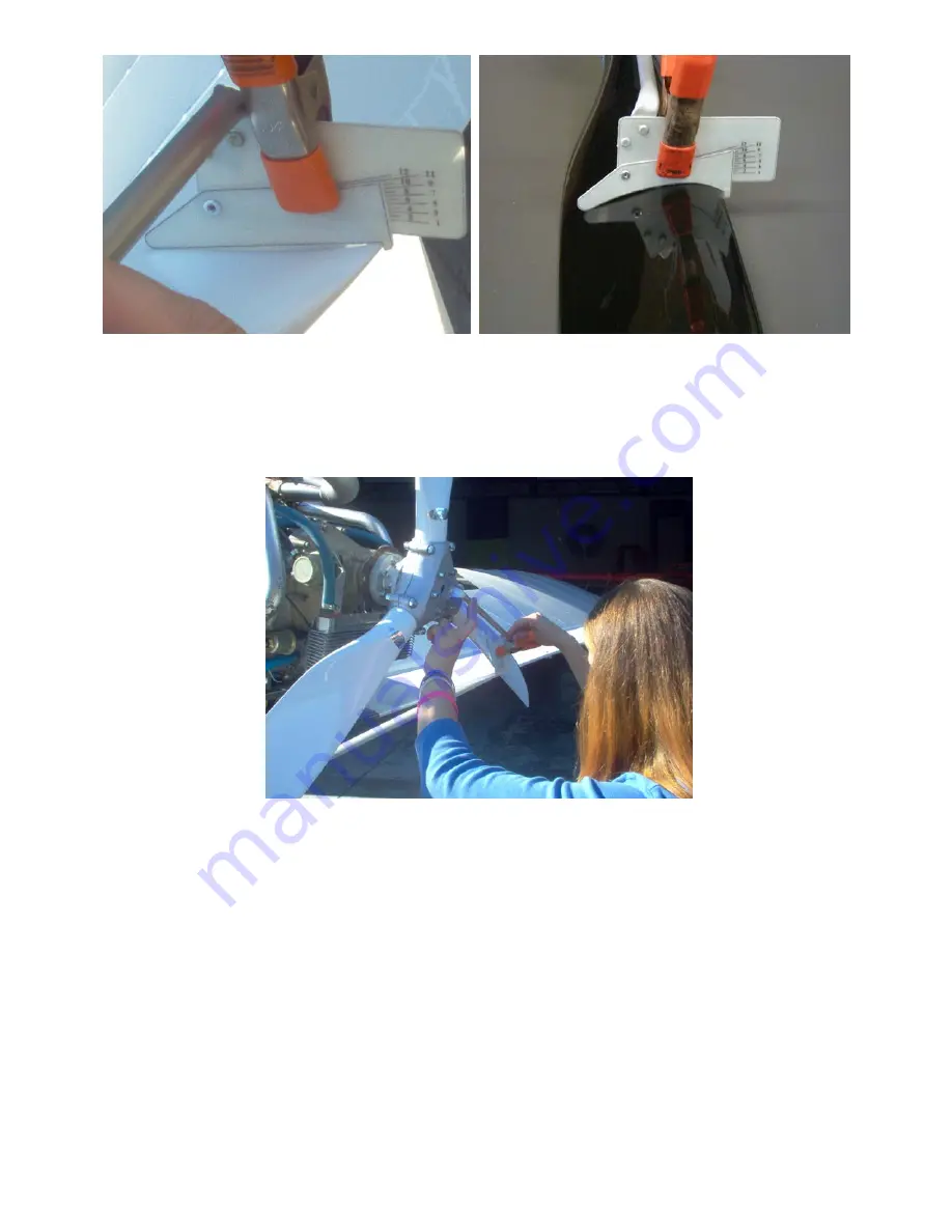
PUSHER TRACTOR
9. For Pusher aircraft
, place the notched end of the protractor against the trailing edge of each prop
blade. For Tractor applications, the notched end should be on the Leading edge of each blade.
Rotate the blade until it sits flat against the leading and trailing edge of the protractor.
IMPORTANT
: Ensure that the ears on the protractor are flush against the hub when the setting the
blade angle. To hold the blade setting, carefully torque the two nuts on the shoulder bolts to 3-4 foot
lbs. Repeat procedure for the other blades.
10. When all blade angles have been set
and using a calibrated torque wrench, tighten the Nyloc
nuts sequentially with 5 ft. lb. increments to
14.5-foot lb.
This will help to insure proper tracking.
Check the pitch of all blades again, and once satisfied, begin torquing the (center) mounting hardware
sequentially, opposing and with 5 ft. lb. increments to
14.5 lb.
A 13mm crows foot on the end of the
torque wrench works well to access the nuts on the backside of the gearbox prop flange. Double-
check the pitch setting again. Do not under torque.
WARNING!!!
DO NOT OVER OR UNDER TORQUE BOLTS! NEVER START ENGINE WITHOUT
PROPER TORQUE ON BOLTS OR DAMAGES INCLUDING LOSS OF PROPELLER, INJURY OR
DEATH MAY RESULT!!!
Appendix E1 Page 3
Summary of Contents for 912 Dragonfly
Page 3: ...Page 2 ...
Page 4: ...Page 3 ...
Page 5: ...Page 4 ...
Page 25: ...Page 24 Drawing 1 ...
Page 27: ...Page 26 Drawing 2 ...
Page 29: ...Page 28 Drawing 3 ...
Page 31: ...Page 30 Drawing 4 ...
Page 33: ...Page 32 Drawing 5 ...
Page 35: ...Page 34 Drawing 6 ...
Page 37: ...Page 36 Note for Hydraulic Brakes see Appendix B Drawing 7 ...
Page 39: ...Page 38 Drawing 8 ...
Page 41: ...Page 40 Drawing 9 ...
Page 43: ...Page 42 Drawing 10 ...
Page 45: ...Page 44 Drawing 11 ...
Page 47: ...Page 46 Drawings 12A 12B ...
Page 49: ...Page 48 Drawing 13 ...
Page 51: ...Page 50 Drawing 14 ...
Page 53: ...Page 52 Drawing 15 ...
Page 55: ...Page 54 Drawing 16 ...
Page 57: ...Page 56 Drawing 17 ...
Page 59: ...Page 58 Drawing 18 ...
Page 61: ...Page 60 Drawing 19 ...
Page 63: ...Page 62 Drawing 20 ...
Page 65: ...Page 64 Drawing 21 ...
Page 67: ...Page 66 Drawing 22 ...
Page 69: ...Page 68 Drawing 23 ...
Page 71: ...Page 70 Drawing 24 ...
Page 73: ...Page 72 Drawing 25 ...
Page 75: ...Page 74 Drawing 26 ...
Page 77: ...Page 76 Drawing 27 ...
Page 79: ...Page 78 Wiring1 jpg Drawing 28a ...
Page 80: ...Page 79 Wiring2 jpg Drawing 28b ...
Page 81: ...Page 80 elecLights jpg Drawing 28c ...
Page 83: ...Page 82 Drawing 29 ...
Page 85: ...Page 84 Drawing 30 ...
Page 92: ...Page 91 Appendix B Brakes Manual for BX1320 BX1000 Appendix B Page 1 ...
Page 93: ...Page 92 Appendix B Page 2 ...
Page 94: ...Page 93 Appendix B Page 3 ...
Page 96: ...Page 95 Appendix B Page 5 ...
Page 97: ...Page 96 Appendix B Page 6 ...
Page 98: ...Page 97 Appendix B Page 7 ...
Page 104: ...Page 103 Figure 1a Description of Display Pages ...
Page 105: ...Page 104 Figure 1b Description of Display Pages ...
Page 138: ...Page 137 Appendix C EIS 4000 912 914 ...
Page 139: ...Page 138 Appendix C EIS 4000 912 914 ...
Page 140: ...Page 139 Appendix C EIS 4000 912 914 ...
Page 141: ...Page 140 Appendix C EIS 4000 912 914 End Appendix C ...
Page 155: ...Page 154 Appendix E2 Powerfin Prop Page 2 ...
Page 156: ...Page 155 Appendix E2 Powerfin Prop Page 3 ...
Page 157: ...Page 156 Appendix E2 Powerfin Prop Page 4 ...
Page 158: ...Page 157 Appendix E2 Powerfin Prop Page 5 ...
Page 159: ...Page 158 Appendix E2 Powerfin Prop Page 6 ...
Page 160: ...Page 159 Appendix E2 Powerfin Prop Page 7 ...
Page 161: ...Page 160 Appendix E2 Powerfin Prop Page 8 ...
Page 162: ...Page 161 Appendix E2 Powerfin Prop Page 9 ...
Page 163: ...Page 162 Appendix E2 Powerfin Prop Page 10 ...
Page 164: ...Page 163 Appendix E2 Powerfin Prop Page 11 End of Appendix E2 ...
Page 187: ...Page 186 By Memphis Soaring FIGURE 3 Common Signals ...


