


Page
105
Congratulations on your purchase of Grand Rapids Technologies' Engine Information System (EIS). We are pleased that
you have chosen our product to meet your aircraft instrumentation needs. You will find this system will enhance your
flying pleasure while increasing your level of safety.
1.
Read This First!
Note for those upgrading the software with a new computer chip. After installing the chip, it may be initialized
to factory default settings by pressing and holding the right button when turning the instrument on. After a delay
of a few seconds, this will set the user-defined pages to the factory configuration.
Advice Before Starting Your Installation: Three steps to make your installation easier.
Step 1. Determine how you would like to arrange your EGT/CHT connections. The EGT/CHT inputs are
numbered 1-4 (1-6 for the Model 6000). You may simply connect EGT1 & CHT1 to cylinder number one
(according to the engine manufacturer’s cylinder numbering). This is common, and works well. For four-
cylinder engines there is also an alternate method. You may wish to connect the EGTs and CHTs so they
correspond to their position on the digital display pages. That is, connecting EGT 1 & CHT 1 to the front left
cylinder (since it appear on the top left position of display page), EGT 2 & CHT 2 to the front right cylinder
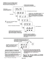
(since it appears on the top right position of the display page), and so on. (Figure 1 illustrates the position of the
data on the display pages.) Either option works well, although personally the latter method is easiest. The main
point is to make sure you know which cylinder corresponds to each of the readings on the instrument so that you
will perform maintenance on the correct cylinder when it becomes necessary.
Step 2. Plan which functions you will wire to each of the 4 auxiliary inputs. Recall that manifold pressure, fuel
pressure, fuel level, vacuum, coolant pressure (and any others that do not have a dedicated input to the
instrument) must be connected through the auxiliary inputs. (The auxiliary inputs may be used for other
functions also, but these are the most common uses.) The only significant consideration concerns the position of
the auxiliary input functions on the labeled pages. Referring to figure 1b, you will note that auxiliary 1, 2, & 3
appear on page 12, and auxiliary 4 appears on the next page. You may prefer to see two or three auxiliary
functions on the same page (for example, left and right fuel levels). This will require wiring them to the first
three auxiliary inputs.
Step 3. Remember that you have complete control over what will be displayed on the two combination pages,
and the digital data displayed on the bar graph pages. You will find this useful for conveniently displaying the
exact data you would like available during your flight
…now on to the installation!
2.
An Overview of Installation & Setup
Installation of the EIS includes the physical mounting of the instrument into the airplane’s instrument panel,
making the electrical connections from the pre-wired cables to the various sensors, and finally setting entries in
the instrument to customize your instrument for your installation. The first two steps are quite obvious. The
entries made to the instrument for your installation tells the instrument such things as how many pulses per
revolution of your engine, units (Fahrenheit or Celsius), etc.
Following these steps, operation of the instrument will be verified by applying power to it. Finally, you will set
your engine limits, and customize the display pages to your liking.
During flight you will use the leaning functions to accurately lean your engine. During the cruise
portion of your flight you will use the tracking functions to continuously monitor your engine for even
momentary signs of developing engine problems. Now let’s get started with the installation by turning
to the section “Installation” which begins on page 110
3.
Using the Engine Information System
Refer to figure 1 for a description of the various display pages, and to figure 2 for an illustration of the
use of the EIS from panel keys to control the operation of the instrument.
Summary of Contents for 912 Dragonfly
Page 3: ...Page 2 ...
Page 4: ...Page 3 ...
Page 5: ...Page 4 ...
Page 25: ...Page 24 Drawing 1 ...
Page 27: ...Page 26 Drawing 2 ...
Page 29: ...Page 28 Drawing 3 ...
Page 31: ...Page 30 Drawing 4 ...
Page 33: ...Page 32 Drawing 5 ...
Page 35: ...Page 34 Drawing 6 ...
Page 37: ...Page 36 Note for Hydraulic Brakes see Appendix B Drawing 7 ...
Page 39: ...Page 38 Drawing 8 ...
Page 41: ...Page 40 Drawing 9 ...
Page 43: ...Page 42 Drawing 10 ...
Page 45: ...Page 44 Drawing 11 ...
Page 47: ...Page 46 Drawings 12A 12B ...
Page 49: ...Page 48 Drawing 13 ...
Page 51: ...Page 50 Drawing 14 ...
Page 53: ...Page 52 Drawing 15 ...
Page 55: ...Page 54 Drawing 16 ...
Page 57: ...Page 56 Drawing 17 ...
Page 59: ...Page 58 Drawing 18 ...
Page 61: ...Page 60 Drawing 19 ...
Page 63: ...Page 62 Drawing 20 ...
Page 65: ...Page 64 Drawing 21 ...
Page 67: ...Page 66 Drawing 22 ...
Page 69: ...Page 68 Drawing 23 ...
Page 71: ...Page 70 Drawing 24 ...
Page 73: ...Page 72 Drawing 25 ...
Page 75: ...Page 74 Drawing 26 ...
Page 77: ...Page 76 Drawing 27 ...
Page 79: ...Page 78 Wiring1 jpg Drawing 28a ...
Page 80: ...Page 79 Wiring2 jpg Drawing 28b ...
Page 81: ...Page 80 elecLights jpg Drawing 28c ...
Page 83: ...Page 82 Drawing 29 ...
Page 85: ...Page 84 Drawing 30 ...
Page 92: ...Page 91 Appendix B Brakes Manual for BX1320 BX1000 Appendix B Page 1 ...
Page 93: ...Page 92 Appendix B Page 2 ...
Page 94: ...Page 93 Appendix B Page 3 ...
Page 96: ...Page 95 Appendix B Page 5 ...
Page 97: ...Page 96 Appendix B Page 6 ...
Page 98: ...Page 97 Appendix B Page 7 ...
Page 104: ...Page 103 Figure 1a Description of Display Pages ...
Page 105: ...Page 104 Figure 1b Description of Display Pages ...
Page 138: ...Page 137 Appendix C EIS 4000 912 914 ...
Page 139: ...Page 138 Appendix C EIS 4000 912 914 ...
Page 140: ...Page 139 Appendix C EIS 4000 912 914 ...
Page 141: ...Page 140 Appendix C EIS 4000 912 914 End Appendix C ...
Page 155: ...Page 154 Appendix E2 Powerfin Prop Page 2 ...
Page 156: ...Page 155 Appendix E2 Powerfin Prop Page 3 ...
Page 157: ...Page 156 Appendix E2 Powerfin Prop Page 4 ...
Page 158: ...Page 157 Appendix E2 Powerfin Prop Page 5 ...
Page 159: ...Page 158 Appendix E2 Powerfin Prop Page 6 ...
Page 160: ...Page 159 Appendix E2 Powerfin Prop Page 7 ...
Page 161: ...Page 160 Appendix E2 Powerfin Prop Page 8 ...
Page 162: ...Page 161 Appendix E2 Powerfin Prop Page 9 ...
Page 163: ...Page 162 Appendix E2 Powerfin Prop Page 10 ...
Page 164: ...Page 163 Appendix E2 Powerfin Prop Page 11 End of Appendix E2 ...
Page 187: ...Page 186 By Memphis Soaring FIGURE 3 Common Signals ...


