Page
181
F:
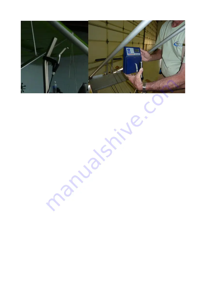
Release Handle
Release Pressure is easily measured with a Digital Postal Scale. Normally 5 lb. 4 oz. 4 to 9 lbs. of
pressure are acceptable. More than 9 lbs. pressure indicates cable needs replacement or there is
excessive resistance somewhere in the system.
2. Limitations
2.1 Introduction
It is important to adhere to the specifications for Installation, Maintenance and Inspection that
have been tested, refined and proven since 1990. This information is found in the Dragonfly
Maintenance Manual and Pilot Operating Handbook (POH) . In order to confirm you have the most
current information, consult manuals posted on the website at: www.pitmanair.com/dragonfly
2.2 Installation
Installation and Maintenance are defined in the Dragonfly Maintenance Manual.
2.3 Loads
Maximum gross vehicle weight to be towed: 562 lbs. (255 Kg.)
Loads are limited by proper installation and used of “Safety Links” commonly referred to as Weak
Links.
Safety Links are made from 130 lb. or 200 lb. Braided Dacron Fishing Line depending upon placement
and loads.
The Single Loop is used to fasten the Towline to the Glider being towed. (Point E in Figure 1)
Solo Glider
TUF LINE BRAIDED DACRON 130 LB. TEST
GREEN SPOT,
or
Tandem Glider
TUF LINE BRAIDED DACRON 200 LB. TEST
GREEN SPOT,
(200 lb. on
Single Loop only)
which can be purchased on the Internet.
The Triple Strength Link is used to fasten the Tow Bridle to the Quick Release. (Point B in Figure 1)
We use
TUF LINE BRAIDED DACRON 130 LB. TEST
GREEN SPOT,
CAUTION: Any increase in Safety Link strength or change of configuration can cause
structural damage and/or allow either or both aircraft to get into unsafe attitudes. Safety Links
must be installed in the configurations outlined within!
Summary of Contents for 912 Dragonfly
Page 3: ...Page 2 ...
Page 4: ...Page 3 ...
Page 5: ...Page 4 ...
Page 25: ...Page 24 Drawing 1 ...
Page 27: ...Page 26 Drawing 2 ...
Page 29: ...Page 28 Drawing 3 ...
Page 31: ...Page 30 Drawing 4 ...
Page 33: ...Page 32 Drawing 5 ...
Page 35: ...Page 34 Drawing 6 ...
Page 37: ...Page 36 Note for Hydraulic Brakes see Appendix B Drawing 7 ...
Page 39: ...Page 38 Drawing 8 ...
Page 41: ...Page 40 Drawing 9 ...
Page 43: ...Page 42 Drawing 10 ...
Page 45: ...Page 44 Drawing 11 ...
Page 47: ...Page 46 Drawings 12A 12B ...
Page 49: ...Page 48 Drawing 13 ...
Page 51: ...Page 50 Drawing 14 ...
Page 53: ...Page 52 Drawing 15 ...
Page 55: ...Page 54 Drawing 16 ...
Page 57: ...Page 56 Drawing 17 ...
Page 59: ...Page 58 Drawing 18 ...
Page 61: ...Page 60 Drawing 19 ...
Page 63: ...Page 62 Drawing 20 ...
Page 65: ...Page 64 Drawing 21 ...
Page 67: ...Page 66 Drawing 22 ...
Page 69: ...Page 68 Drawing 23 ...
Page 71: ...Page 70 Drawing 24 ...
Page 73: ...Page 72 Drawing 25 ...
Page 75: ...Page 74 Drawing 26 ...
Page 77: ...Page 76 Drawing 27 ...
Page 79: ...Page 78 Wiring1 jpg Drawing 28a ...
Page 80: ...Page 79 Wiring2 jpg Drawing 28b ...
Page 81: ...Page 80 elecLights jpg Drawing 28c ...
Page 83: ...Page 82 Drawing 29 ...
Page 85: ...Page 84 Drawing 30 ...
Page 92: ...Page 91 Appendix B Brakes Manual for BX1320 BX1000 Appendix B Page 1 ...
Page 93: ...Page 92 Appendix B Page 2 ...
Page 94: ...Page 93 Appendix B Page 3 ...
Page 96: ...Page 95 Appendix B Page 5 ...
Page 97: ...Page 96 Appendix B Page 6 ...
Page 98: ...Page 97 Appendix B Page 7 ...
Page 104: ...Page 103 Figure 1a Description of Display Pages ...
Page 105: ...Page 104 Figure 1b Description of Display Pages ...
Page 138: ...Page 137 Appendix C EIS 4000 912 914 ...
Page 139: ...Page 138 Appendix C EIS 4000 912 914 ...
Page 140: ...Page 139 Appendix C EIS 4000 912 914 ...
Page 141: ...Page 140 Appendix C EIS 4000 912 914 End Appendix C ...
Page 155: ...Page 154 Appendix E2 Powerfin Prop Page 2 ...
Page 156: ...Page 155 Appendix E2 Powerfin Prop Page 3 ...
Page 157: ...Page 156 Appendix E2 Powerfin Prop Page 4 ...
Page 158: ...Page 157 Appendix E2 Powerfin Prop Page 5 ...
Page 159: ...Page 158 Appendix E2 Powerfin Prop Page 6 ...
Page 160: ...Page 159 Appendix E2 Powerfin Prop Page 7 ...
Page 161: ...Page 160 Appendix E2 Powerfin Prop Page 8 ...
Page 162: ...Page 161 Appendix E2 Powerfin Prop Page 9 ...
Page 163: ...Page 162 Appendix E2 Powerfin Prop Page 10 ...
Page 164: ...Page 163 Appendix E2 Powerfin Prop Page 11 End of Appendix E2 ...
Page 187: ...Page 186 By Memphis Soaring FIGURE 3 Common Signals ...


