50
50
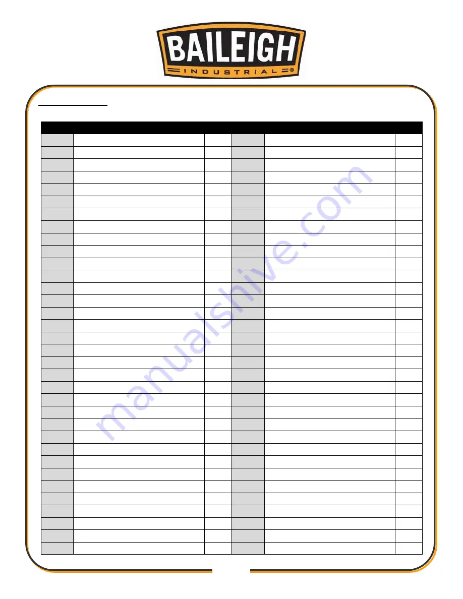
Stand Parts List
Ite
m
Descr
i
ption
Qty
Item Description
Qty
401
S
t
and
1
435
Rig
h
t
U
p Plate
1
4
0
2
Power Pla
t
e
2
436
Gas Spri
n
g 200N
2
403
F
la
t
Wash
er M
6
28
437
Cover
1
"
40
4
Screw M6 x 12
28
438
L
oose Leaf
2
405
Sw
it
ch Box
2
439
L
ock Washer M8
8
406
Box Pla
t
e 1
1
440
N
ut M8
8
407
Cap Screw M4 x8
4
441
Screw M8 x 20
4
408
Screw M6 x12
4
442
Fla
t
Wash
e
r M8
4
409
Flat Washer
4
443
Chu
t
e Plate
1
410
Front Pla
t
e
1
444
Chute
1
411
P
l
ate
2
445
Screw M5 x 16
6
412
Fron
t
Press Plate
1
446
Back Press Plate
2
413
Screw M5 x 12
9
44
7
Screw M5 x 16
4
414
On / Off Swi
t
ch
1
448
Ma
i
n Contro
l
Switch
1
4
1
5
Eme
r
g
en
cy Stop Swi
tc
h
1
449
Box Cover 1
1
4
1
6
Adjust Speed Knob
1
450
Main Switch Box
2
417
Infeed Switch
1
451
Box Cover 2
1
418
Screw M4 x 10
4
452 Emergency Stop Sw
i
tch
1
419
Digital Contro
l
1
453
Left Up Pla
t
e
1
420
H
andle
2
454
Limit Switch
2
421
Label
1
455
Plate
2
422
Screw M3
.
9 x20
8
456
Lock Washer M
4
423
Screw M3
.
5 x 16
4
457
Cap Screw M4 x 30
6
424
Box Plate 2
1
458
Screw M10 x 25
8
425
Box
1
459
Hang
4
426
Right Protect Plate
1
460
Left Cover Plate
1
427
Screw M6 x 16
4
461
Limit Switch
1
428
Right Cover P
l
ate
1
462
Strain Relief
1
429
F
lat Washer M6
4
463
Power Cord
1
430
Screw M6 x 16
4
464
Switch
1
431
H
andle
1
465
Screw M6 x 20
4
432
Cap Screw M5 x 12
4
466
Knob M8 x 18
1
433
Bolt M8 x 25
1
467
Flat Washer M8
1
434
Nut M8
1
468
Spec
i
al Nut M8
1
Summary of Contents for IP-2511-HD
Page 39: ...36 36 ELECTRICAL SCHEMATIC...
Page 40: ...37 37...
Page 41: ...38 38...
Page 42: ...39 39...
Page 43: ...40 40 Electrical Cabinet Layout...
Page 44: ...41 41 CUTTERHEAD PARTS DIAGRAM...
Page 46: ...43 43 TABLE PARTS DIAGRAM...
Page 48: ...45 45 TABLE ROLLER PARTS DIAGRAM...
Page 50: ...47 47 INFEED PARTS DIAGRAM...
Page 52: ...49 49 STAND PARTS DIAGRAM...
Page 54: ...51 51 NOTES...
Page 55: ...52 52 NOTES...


