28
28
5. Determine which side of the table you will adjust to bring
the table parallel with the cutterhead (within 0.01mm).
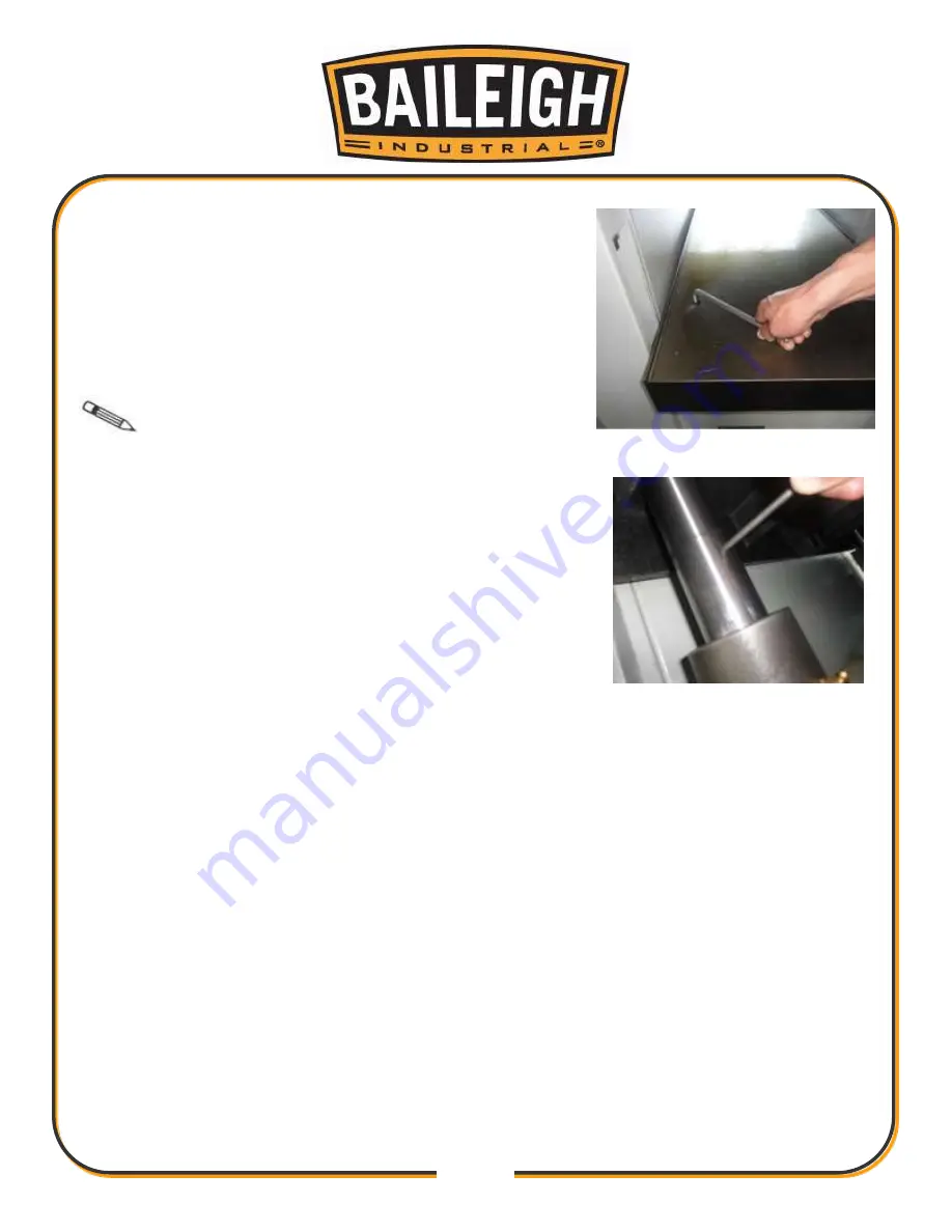
6. Use the 12mm hex wrench to loosen the table elevation
housing bracket cap screws for that side of the table (Fig.
15).
7. Insert the long end of the 1/4" (6mm) round bar into the
leverage hole and turn the column until you are satisfied
with the table parallelism from side-to-side. (Fig. 16).
Note
: The slight deformation of the rubber
elevation screw cover is normal and will not affect table
movement.
8. Tighten the cap screws holding the column in place.
Fig. 15
Fig. 16
Summary of Contents for IP-2511-HD
Page 39: ...36 36 ELECTRICAL SCHEMATIC...
Page 40: ...37 37...
Page 41: ...38 38...
Page 42: ...39 39...
Page 43: ...40 40 Electrical Cabinet Layout...
Page 44: ...41 41 CUTTERHEAD PARTS DIAGRAM...
Page 46: ...43 43 TABLE PARTS DIAGRAM...
Page 48: ...45 45 TABLE ROLLER PARTS DIAGRAM...
Page 50: ...47 47 INFEED PARTS DIAGRAM...
Page 52: ...49 49 STAND PARTS DIAGRAM...
Page 54: ...51 51 NOTES...
Page 55: ...52 52 NOTES...


