19
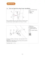
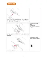
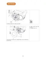
direction as show by the arrows in the picture above) to release the female buckles on
the upper cover. Push the upper cover in the direction of moving towards Buckle 3 to
fully open the upper cover.
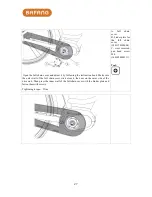
Open the cabling box, link all cables to the drive unit and put all connectors in the
cabling box according to the cabling diagram printed on the upper cover of the cabling
box (see C in the picture above).
After matching all male connectors with female connectors, cover the cabling box
with the upper cover and thread the cables through cable clips (D in the picture above)
following the principle of "upper thin cables and lower thick cables" to ensure that the
cables are neatly arranged.
C. cabling layout
(2307070000001)
D. cable clips
(1401300000001)
Summary of Contents for MM G31.250
Page 9: ...9...
Page 50: ...50 Fault Alert Interface...


