background image


Carry & Carry XL  


Seite / 

Page

 12 


Kundenservice / 

Customer service


Bei Ihrem Händler oder direkt bei: 

At your dealer or directly at:


B-TEC GmbH, Zunftweg 6-8   
31303 Burgdorf / Ehlershausen , Germany 
Tel.: +49(0)5085-97100-0, Fax: +49(0)5085-97100-30 
Email: [email protected] 
www.btecsystems.de 


5.


Bedienung / 

Operation 


 Anheben / 

Lifting 


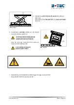
1.


Heruntergefahrene  Hebebühne  über  die  Auffahrrampen  in  Längsrichtung  befahren  und  mittig 
positionieren.  Handbremse  anziehen  und  Gang  einlegen  (Bzw.  Parkposition  bei  Automatik 
Fahrzeugen). Fahrzeug gegen Wegrollen sichern. 

Drive on the lowered lift to a central position, apply parking brake and engage the first gear (Or 
parking position in case of automatic vehicles). Secure the vehicle against rolling away.  


2.


Handventil  in  "auf"-Stellung  bringen  um  die  Hebebühne  anzuheben.  Während  des  Hebens  auf 
sicheren Stand des Fahrzeugs achten.


Put the hand-valve in "auf"-position to lift the platform. During lifting, please observe the car and 
check its stability on the lift. 


3.


Wenn  die  gewünschte  Höhe  oder  der  maximale  Hub  erreicht  ist,  Hebel  in  0-Stellung  bringen. 
Stellen Sie sicher, dass die Fallsicherung auf der gewünschten Höhe beidseitig in der Verzahnung 
eingreift. Dies ist an einem deutlichen Klack-Geräusch während des Hochfahrens zu erkennen. 


If the wished or maximum height is reached, put the hand-valve in 0-position. Ensure that the safety 
gripping device snaps in properly at the wished height. A clear clicking sound indicates snapping.   


Das Handventil darf nicht mit einem Gegenstand verklemmt oder nach Erreichen der 

maximalen Höhe in „auf“-Stellung gehalten werden! 


Don’t block the hand-valve with objects and don’t keep the hand-valve in “auf”-

position after reaching the maximum height!


Absenken / 

Lowering 


Zum Absenken Handhebelventil in "ab"-Stellung bringen und unter Beobachtung der Hebebühne, der 
näheren Umgebung und des Fahrzeuges die Hebebühne bis zur Endstellung bringen. Halten Sie das 
Handhebelventil  in  "ab"-Stellung  bis  keine  Luft  mehr  aus  dem  Handhebelventil  austritt  und  das 
Manometer 0 bar anzeigt. 

For lowering, put the hand-valve to position "ab". While lowering the lift, please observe the lift, the 
surroundings and the car. If the lift has reached the lowest position, drive the car slowly and carefully 
from the lift. Keep the hand-valve in position "ab" until no more air leaves through the hand-valve and 
the manometer shows 0 bar. 


Vor dem Absenken darauf achten, dass sich kein Hindernis oder Mensch im Bereich 

der Hebebühne befindet.


Before lowering, ensure that there is no object or person in the area of the lift!


Die Sicherheitshinweise in Abschn. 2 sind bei der Inbetriebnahme und Benutzung der 

Hebebühne unbedingt einzuhalten.

 The safety instructions in sec. 2 must be fallowed 

during commissioning and operation! 

Summary of Contents for Carry

Page 1: ...info btecsystems de www btecsystems de Carry Carry XL Fahrzeug Hebeb hne Vehicle Lift Betriebsanleitung und Pr fbuch f r Fahrzeug Hebeb hne Carry Carry XL Operating Manual and Test Log Book for Vehicl...

Page 2: ...issued under the sole responsibility of the manufacturer The object of the declaration is in conformity with the relevant Union harmonisation legislation If you modify the machine without our explicit...

Page 3: ...3 4 Technische Daten Carry XL EB Specifications Carry XL EB 9 3 5 Pneumatikplan Pneumatic Diagram 10 3 6 Ersatzteilnummern Spare Parts Ordering Numbers 10 4 Pflege und Wartung Care and Maintenance 11...

Page 4: ...ig durchzuf hrende Sicherheitspr fungen Das Formblatt darf ausschlie lich von bef higten Personen Personen mit ausreichender Kenntnis und Erfahrung oder Monteur des Herstellers oder Sachverst ndigen...

Page 5: ...sich die gesetzl Gew hrleistungsfrist auf 18 Monate Zweischichtbetrieb bzw 12 Monate Dreischichtbetrieb Sie beginnt mit dem Abgang der Lieferungen ab Werk Die Gew hrleistung erlischt vorzeitig wenn d...

Page 6: ...uge zur ckzuf hren sind The manufacturer is not liable for damages caused by changes of the lift that have not been specifically authorised in written form by the manufacturer Furthermore the manufact...

Page 7: ...ll the time the lift goes up or down Bei jedem Hub oder Senkvorgang ist der Bereich unmittelbar um die Hebeb hne und die Hebeb hne selbst auf Fremdk rper zu pr fen Insbesondere in der N he des Luftfed...

Page 8: ...a load distribution of ca 3 2 up to a total weight of 3300 kg Carry and 3500 kg Carry XL The intended purpose is the temporary lifting of vehicles with four wheels for bodyworks The vehicle stands on...

Page 9: ...Auffahrrampen und berfahrsperren Dimension without ramps or overtravel barriers 3620 mm x 1900 mm Auffahrbreite Driving width Ca 960 mm 1800 mm Luftanschluss max Druck Pmax Compressed air supply outl...

Page 10: ...m B hnenma e ohne Auffahrrampen und berfahrsperren Dimension without ramps or overtravel barriers 3770 mm x 1900 mm Auffahrbreite Driving width Ca 995 mm 1875 mm Luftanschluss max Druck Pmax Compresse...

Page 11: ...ne Auffahrrampen und berfahrsperren Dimension without ramps or overtravel barriers 4230 mm x 2200 mm Auffahrbreite Driving width Ca 1060 mm 2100 mm Luftanschluss max Druck Pmax Compressed air supply o...

Page 12: ...mm B hnenma e ohne Auffahrrampen und berfahrsperren Dimension without ramps or overtravel barriers 4230 mm x 2200 mm Auffahrbreite Driving width Ca 1095 mm 2175 mm Luftanschluss max Druck Pmax Compre...

Page 13: ...ring 10000077 I Befestigungswinkel Set 4 Stk Mounting brackets Set 4 pcs 10000099 Rolle Auffahrrampe inkl Sicherung Wheel for ramps incl locking ring 10000097 Halter f r Auffahrrampe Paar Holder for r...

Page 14: ...wing S mtliche beweglichen Teile sind zu reinigen Nicht mit einem Hochdruckreiniger oder Dampfreiniger und mit silikonfreiem Fett einzufetten Insbesondere die Gelenkbolzen die Scheren die Gleitst cke...

Page 15: ...maximum height is reached put the hand valve in 0 position Ensure that the safety gripping device snaps in properly at the wished height A clear clicking sound indicates snapping Das Handventil darf n...

Page 16: ...chlie end wieder heruntergelassen werden kann If the lift remains for a longer time in lifted position ensure that the pneumatic components are still under pressure Eventually you have to lift up the...

Page 17: ...lve 9 Gitterrost Grating Carry S EB 4 31 18 19 20 21 22 23 24 25 x 1 x 2 x 2 x 2 x 4 x 1 x 2 x 4 x 2 EB x 4 B13 x 8 B13 x 4 B10 5 x 8 B8 4 x 4 M16 x 4 M12 x 8 M10 x 8 M8 x 4 M12 x 80 x 2 x 1 x 1 M12 x...

Page 18: ...lly in Scope of Delivery Auffahrrampe links 32 und rechts 33 Ramp left 32 and right 33 Fu schutzbefestigungsleiste 34 und Fu schutzmatte 35 Foot protection holding strip 34 and foot protection pad 35...

Page 19: ...aurahmen f r Carry EB Carry XL EB Optional for Carry EB Carry XL EB Einbaurahmen Mittelteil Mounting frame central part 26 Einbaurahmen Endteil Mounting frame end part 27 M6 x 8 B6 4 x 8 Senkschraube...

Page 20: ...tinuous usage at temperatures above 50 C can shorten the lifetime of the air spring Bei Betrieb der Hebeb hne in einer explosionsf higen Atmosph re Ex Zone ist das angehobene Fahrzeug kundenseitig an...

Page 21: ...ring the pallet with the lift to the installation site 2 Ausleger 2 berfahrrampen 3 und B hnenzubeh r vom Grundk rper 1 herunternehmen Remove the outriggers 2 overtravel ramps 3 and lift equipment fro...

Page 22: ...undk rper vorsichtig seitlich von der Palette herunter schieben Abb 8 4 ACHTUNG VERLETZUNGSGEFAHR SICHERHEITSSCHUHE TRAGEN Push the main part down from the pallet very slowly and carefully Fig 8 4 CAU...

Page 23: ...t im Lieferumfang enthalten mindestens 120 mm tief bohren Abb 8 6 Drill the fixing hole with rock drill 16 B Not included in the scope of delivery at least 120 mm deep Fig 8 6 Abb Fig 8 6 Abb Fig 8 7...

Page 24: ...ieben und festschrauben Abb 8 10 11 Slide the outriggers 2 into the lift 1 and fix those Fig 8 10 11 Montageteile Assembling parts 4 x M12x45 Schrauben Bolts 15 4 x M12x40 Schrauben Bolts 16 8 x M12 s...

Page 25: ...for the overtravel ramps with rock drill 8 at least 55mm deep comp fig 8 6 knock the small anchor pin through the ramp in the ground 13 comp fig 8 7 8 and fix them 20 Nm fig 8 14 Montageteile Assembl...

Page 26: ...ng in ground lifts ensure that notches show to the outside 19 Gitterroste 4 in die daf r vorgesehenen Ausschnitte in den Auslegern 2 einlegen Place the gratings 4 in the designated gaps of the outrigg...

Page 27: ...r L mit einem Durchmesser von mindestens 70 mm zum Herausf hren der Druckluftschl uche notwendig Dieses darf maximal in einem Bogen von 2 x 45 verlegt werden For the built in version of the lift you n...

Page 28: ...Technical changes and errors reserved 1100 1930 1110 3785 1365 100 415 L A A B B W 1565 O70 max 45 Grubentiefe Pit depth 160 mm 1100 2230 1410 4385 1365 100 565 L A A B B W Grubentiefe Pit depth 160 m...

Page 29: ...r schwei en Dadurch werden sp tere Wartungs und Reparaturarbeiten erschwert The lift for mounting in ground has to be supported at 6 locations A1 A6 as shown in the figures on the next pages We recomm...

Page 30: ...e Page 27 Aufnahmepunkte Carry EB Loading Points Carry EB Abb Fig 8 21 Aufnahmepunkte Loading Points Carry EB 160 min 998 600 1650 860 1300 860 1300 3305 160 A1 A2 A3 A4 A5 A6 Ausgang Druckluftschl uc...

Page 31: ...28 Aufnahmepunkte Carry XL EB Loading Points Carry XL EB Abb Fig 8 22 Aufnahmepunkte Loading Points Carry XL EB 160 min 998 600 1650 1160 1580 1160 1580 3900 160 A1 A2 A3 A4 A5 A6 Ausgang Druckluftsc...

Page 32: ...d B hnenkonstruktion allgemein Condition construction of the lift steel 12 Festigkeit der Schrauben fixity of bolts Anmerkungen Remarks ____________________________________________________________ Dat...

Reviews: