Avtech AVT583 User Manual Download Page 5


CONNECTION 

1. DC12V 

Input 

Terminal 

Connect the power terminal of the camera to a DC 12V regulated power supply. 

NOTE: 

Please use the correct power adaptor, DC12V (regulated), to operate this unit. The power 

tolerance of this unit is DC12V ± 10%. Over maximum DC 12V power input will damage this 

unit.


2.  Video Output Connector (VIDEO OUT) 

Connect the camera video output to the video input of a DVR with 75

 coaxial cable. 

NOTE:

 To ensure the camera has sufficient protection against moisture, an extra waterproof 

measure, such as by using an insulating tape, must be used to cover the power and video 

connectors after connection.


PTZ CONTROL 

NOTE:

 The panel below is available only when the camera is used with our brand’s HD CCTV DVR, 

and not all functions in the panel are supported for this camera.  

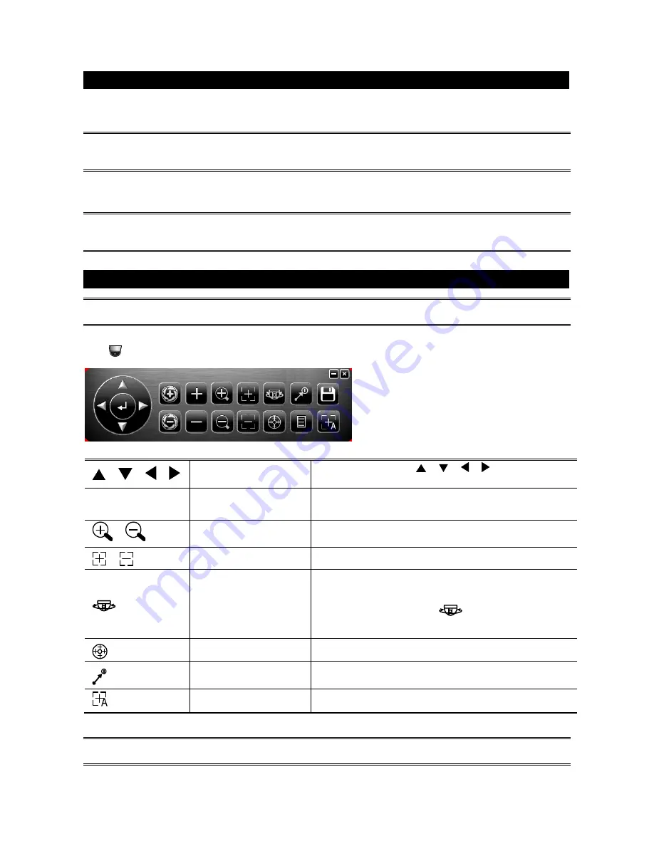
Right-click to return to the live view, and click the channel with this speed dome camera connected. Then, 
click 

  on the bottom left side of the screen to show the PTZ control panel. 


 / 

 /   / 


Up / Down / Left / Right

Click the arrow keys (

 /   /   / 

) to move the 

camera lens up / down / left /right. 

 / 


Zoom in / out max 

Click to zoom in on the image to the largest / zoom out 
on the image to its original size. 

 / 


Zoom in / out 

Click to zoom in / out the image. 

 / 


Focus near / far 

Click to adjust the focus of the image. 


Auto mode 

Click to activate the auto function. 

Before using it, you need to assign a specific function 
that will be enabled when “

” is clicked.   

For details, please see “CAMERA PARAMETERS”. 


Auto tracking 

Click to start auto tracking, and click again to stop. 


Preset point 

Click to configure or go to the preset point you want to 
see. For details, please see “SEQUENCE SETUP”. 


Auto Focus 

Click to automatically adjust the focus of the camera. 


NOTE:

 PTZ control is also available via the optional USB joystick and EagleEyes. For details, please 

check their respective user manuals. 


Summary of Contents for AVT583

Page 1: ...to constitute a risk of electric shock to persons This exclamation point within an equilateral triangle is intended to alert the user to the presence of important operating and maintenance servicing i...

Page 2: ...ABLE OF CONTENTS SPECIFICATIONS 1 PACKAGE CONTENT 2 INSTALLATION 2 CONNECTION 3 PTZ CONTROL 3 CAMERA PARAMETERS 4 AUTO PAN SETUP 6 CRUISE SETUP 7 SEQUENCE SETUP 8 CAMERA GUARD 10 AUTO TRACKING SETUP 1...

Page 3: ...1 6 S N Ratio More than 48dB AGC OFF Shutter Speed 1 60 1 50 to 1 100 000 sec Lens f4 7 94mm F1 6 Wide 3 5 Tele Lens Angle Horizontal 1X 60 8 20X 3 4 Vertical 1X 35 3 20X 1 9 Diagonal 1X 68 3 20X 3 8...

Page 4: ...fore replacing it back Step2 Pass the cables to be connected through the bracket and fasten the bracket to the wall ash shown in Figure 2 Figure 1 Figure 2 Step3 Hook the camera and the bracket togeth...

Page 5: ...n to the live view and click the channel with this speed dome camera connected Then click on the bottom left side of the screen to show the PTZ control panel Up Down Left Right Click the arrow keys to...

Page 6: ...s selected in the PTZ mode There are three options AUTO PAN SEQUENCE and CRUISE AUTO PAN Pan within the range specified in CRUISE CONFIG SEQUENCE Patrol based on the sequence group specified in CRUISE...

Page 7: ...DENOISE Click and drag the slider to adjust the level from 0 5 to decrease the noise shown in the dark environment 2D denoise analyzes only a single picture to decrease the noise The moving objects c...

Page 8: ...eft side of the screen Icon Function Description Left limit Move the slider to where you want to set as the most left side of the surveillance area and click to set Right limit Move the slider to wher...

Page 9: ...ute There are 4 groups to be used b Move to the scene you want the cruise to be started c Click Record Then drag and hold the mouse to move the camera for route planning and scroll the mouse to zoom i...

Page 10: ...aring on the DVR status bar NOTE Up to 256 preset points could be configured Step4 Repeat Step3 until you ve added all the points you need or click to return to the Goto panel Step5 In the Goto panel...

Page 11: ...ct how long the area patrolling lasts in minute The options are 2 3 and 5 DWELL TIME Select the time in second after which to move to the next point The time ranges from 3 to 60 PAN SPEED Select how f...

Page 12: ...lect the channel which connects this camera and click SETUP to enter the menu of camera parameters ADVANCED CONFIG CAMERA CH1 CH2 CH3 CH4 DETECTION MENU SETUP ALERT NETWORK DISPLAY RECORD DCCS F W 101...

Page 13: ...11 Step4 Return to the address book of EagleEyes and enable Guard The camera will fix at the point after the time specified in Step2 unless the Guard status is disabled...

Page 14: ...ght limit Move the slider to where you want to set as the most right side of the surveillance area and click to set Tilt angle Move the slider to select the tilt range of the surveillance area Zoom ra...

Reviews: