background image

83

User Manual

select the number desired and press ‘ENTER’. The default setting is OFF (00.00).

14.3.4 AIRSPACE AHEAD ALARM

If your projected track will cross an airspace sector, an alarm will sound and a

warning box will appear on the screen. If there is an altitude limitation to the

airspace, we will display an alarm if your current altitude is within 500 feet of

the limitations.

To set the time interval for the alarm:

> ‘MENU’ 1 sec + “ALARM SERUP: + ‘ENTER’ “AIRSPACE AHEAD ALARM” + ‘ENTER’

After pressing 

‘ENTER’ 

a box will appear with 00.00. Using the cursor key,

select the number desired and press 

‘ENTER

’.

The default setting is OFF (00.00).

In addition, you can select the category of airspace associated with the alarm.

To select the categories:

> ‘MENU’ 1 sec ‘MENU; + “ALARM SETUP”

Use the cursor key to select each category of airspace and turn ON/OFF the alarm for

that category. The time interval set above is for all airspace selected as ON.

14.3.5 EVENT LOG

The Event Log page contains information on Event as Power On, Power Off, GPS Fix

Lost, and so on. For each Event, the Event name, Time and Date are shown.

To Select the Event LOG page:

> ‘MENU’ 1 sec. + “SYSTEM SETUP” + ‘ENTER’ + “ALARM SETUP” + ‘ENTER’ + “EVENT LOG...”

+ ‘ENTER’

14.3.6 CLEAR EVENT LOG

Clears the Event Log memory and starts new:

> ‘MENU’ 1 sec. + “SYSTEM SETUP” + ‘ENTER’ + “ALARM SETUP” + ‘ENTER’ + “CLEAR EVENT

LOG” + ‘ENTER’

After pressing ‘ENTER’ a window appears: press ‘ENTER’ to confirm dele-

tion (or ‘CLEAR’ to abort function). The message “DONE” will appear con-

firming the action.

14.4 TRACK SET-UP

Track is the actual course traveled, which the EKP-IV can display as a series of

connected dots.

The interval setting can be defined by the pilot.

> ‘MENU’ 1 sec. + “SYSTEM SETUP” + ‘ENTER’ + “TRACK SETUP” + ‘ENTER’

Summary of Contents for EKP IV

Page 1: ...User Manual Via Caboto 9 54036 Marina di Carrara MS ITALIA E mail info avmap it ...

Page 2: ...y damage due to shipping misuse negligence tampering or improper use Servicing performed or attempted by anyone other than an authorized AvMap representative Attenzione L esposizione del display ai raggi ultravioletti può accorciare la vita dei cristalli liquidiusatinelvostroplottercartografico Questolimiteèdovutoallatecnologiacostruttivadegliattualidisplay Evitare inoltre che il display si surris...

Page 3: ...n is a very important operation and must be done carefully Since the surface is covered by a antireflective coating the procedure for cleaning all the sur faces can be performed using the following procedure You need a tissue or lens tissue and a cleaning spray containing Isopropanol a normal spray cleaner sold for the PC screen for ex ample PolaClear by Polaroid Fold the tissue or lens tissue int...

Page 4: ...6 User Manual ...

Page 5: ... 5 3 DOWN OR UP LOAD FLIGHT PLANS TRACKS 22 2 6 SYSTEM SETUP OPTIONS 23 2 7 DATA ENTRY 24 3 The Moving Maps 25 3 1 OPERATING MODES 25 3 1 1 CURSOR MODE 25 3 1 2 HOME SCREEN AMPLIFIER MODE 25 3 1 3 AUTO ZOOM MODE 26 3 2 DATA WINDOW 26 3 3 AUTOMATIC INFO 27 3 4 CURSOR OR POSITION MODE 27 3 4 1 AIRSPACE INFORMATION 28 3 4 2 FULL INFORMATION 28 3 4 3 PROJECT RADIAL 28 3 4 4 A B FUNCTION 28 3 4 5 WAYPO...

Page 6: ... 7 3 2 WAAS 53 7 3 3 DIFFERENTIAL GPS 53 7 3 4 MONITORING CONTROLLING THE GPS 54 7 3 5 GPS INFORMATION SOURCES 54 8 Waypoint Database 55 8 1 USER WAYPOINTS MOVING MAP 55 8 1 1 CREATING USER WAYPOINTS MOVING MAP 55 8 1 2 SAVING PRESENT POSITION MOVING MAP METHODS 56 8 1 3 EDITING USER WAYPOINTS MOVING MAP METHODS 56 8 1 4 DELETING USER WAYPOINTS MOVING MAP METHODS 56 8 2 USER WAYPOINTS DATABASE MET...

Page 7: ...EAD UP RESPONSE 81 14 3 ALARM SET UP 82 14 3 1 ARRIVAL ALARM RADIUS 82 14 3 2 XTE ALARM RANGE 82 14 3 3 WAYPOINT ALARM RADIUS 82 14 3 4 AIRSPACE AHEAD ALARM 83 14 3 5 EVENT LOG 83 14 3 6 CLEAR EVENT LOG 83 14 4 TRACK SET UP 83 14 4 1 TRACK DISPLAY 84 14 4 2 TRACK RECORDING STEP 84 14 4 3 CLEAR TRACK 84 14 4 4 REMAINING TRACK 84 14 5 UNITS SET UP 84 14 5 1 DISTANCE UNIT 85 14 5 2 SPEED UNITS 85 14 ...

Page 8: ...OOTING 91 15 4 1 POWER 91 15 4 2 GPS FIX 91 15 4 3 WHEN NOTHING ELSE WORKS 92 15 4 4 CUSTOMER SUPPORT 92 15 5 SYSTEM TEST 93 15 5 1 RAM MENU 93 15 5 2 C CARD menu 94 15 5 3 SERIAL PORTS 94 Appendix A Terms 96 Appendix C Map Datum 99 Appendix D ICAO codes 99 Appendix E C MAP Aviation Cartridge Options 103 Appendix F C MAP Data Transfer 104 ...

Page 9: ...Designed as a sophisticated navigation information cen ter the features of the EKP IV allow the user to Track information and navi gate to points of interest Equipped with C MAP NT cartography the EKP IV system can be used either with a C MAP NT Compact Flash data card or as a Track plotter using the internal background map The EKP IV can be connected to an external GPS or position receiver via a ...

Page 10: ...rs 7 Points per Track 5000 Step by Distance Auto 20 100 500 Mt 1Km 5 30 Sec 1 Min Cartographic Functions Worldwide Background Built in Continental Cartography Coordinates System DDD MM SS DDD MM mm DDD MM mmm UTM OSGB MGRS North Reference Auto Zoom Map Presentation Aero Terrestrial Aeronautical Marine POI Settings Selective and cycled Display VFR Airports VOR NDB Intersections Vertical Obstruction...

Page 11: ...it selection KM NM SM Speed Unit selection MPH KTS KMH Altitude Unit selection FT FL MT Depth Unit selection FT FM MT Fuel Unit selection GAL LIT LB KG BGAL Descent Rate selection FT MIN M S DEG Temperature Unit C F Alarms handling Arrival XTE Waypoint Alarm Radius Airspace Database Airports VOR NDB Intersections POI objects User Waypoints File Manager Calculator Countdown Timer Elapsed Timer Trip...

Page 12: ...F 25 C to 70 C Memory Non volatile with battery back up Keyboard Backlighted silicon rubber 1 2 BASIC Fig 1 2 How to insert the Compact Flash The EKP IV is controlled by using 10 keys As you press a key a single audio beep confirms the key action every time the key pressed is not valid three rapid beeps sound indicating that no response is available POWER Key For quick access to the GPS status tap...

Page 13: ...om your EKP IV NOTE The EKP IV is an aid to navigation It does not replace paper charts and good judgement 1 3 1 THE MOVING MAP Before starting connect the EKP IV to power and place the antenna with a clear view of the sky Press POWER to start the EKP IV Press ENTER to exit from the Warn ing page and enter the Moving Map mode The Moving Map is the default state displaying the Moving Map screen and...

Page 14: ...me mode will allow the user to pan away from his present posi tion to view other parts of the map and return to present position automati cally when no buttons are pushed for a pre determined amount of seconds Auto Zoom mode will keep your present position and your destination in the screen at all times The screen will automatically zoom in as you get closer To shut off this function simply select...

Page 15: ...n at the set time interval if the current speed and heading are kept This allows the pilot to correct for wind drift in real time right from the moving map To select course predictor MENU 1 sec SYSTEM SETUP ENTER FIX SETUP ENTER COURSE PREDIC TOR ENTER 1 3 6 GOTO GoTo sets a 1 leg course from the present position to any location or selected Waypoint To activate a GoTo Flight Plan move the cursor t...

Page 16: ...e database item and press GOTO again to acti vate To deactivate press GOTO and select DEACTIVATE 1 3 7 DATABASE The Database function allows the user to access information stored in the data cartridges on Airports VOR s NDB s Intersections and User Waypoints Searching the Database allows the user to activate GoTo Flight Plans and lo cate the item on the map There are two methods of accessing the D...

Page 17: ...The Power key POWER press and hold to turn the EKP IV On POWER 3 sec once the EKP IV has been turned On turns the EKP IV Off POWER immediately release once the EKP IV has been turned On displays the Brightness and the Contrast Menu The Page key Displays a list of the 20 nearest objects relative to fix position or cursor posi tion if no fix is available The GoTo key Activates a Flight Plan to the c...

Page 18: ...hy for details see par 3 5 9 2 2 TURNING THE EKP IV ON OFF Before powering On the EKP IV check for the correct voltage 10 35 Volt DC 2 2 1 TURNING ON Press and hold POWER for 1 second The EKP IV emits one rapid beep sound and a Title page containing information about the Product name Software version library version and cartridges installed is displayed This data can also be viewed in the About pa...

Page 19: ...e and the GPS State are shown 2 4 SELECTING THE LANGUAGE It is possible to select the language in which the information is displayed for screen labels menus and options but it does not affect the map information The default setting is English MENU 1 sec SYSTEM SETUP ENTER GENERAL SETUP ENTER LANGUAGE ENTER Choose the language you want and press ENTER again to confirm 2 5 EXTERNAL CONNECTIONS 2 5 1...

Page 20: ...e Output NMEA0183 messages are the following APA APB BOD BWC GGA GLL HSC RMA RMB RMC VTG WCV XTE see Appendix F for more details on NMEA sentences BOD BWC GGA GLL HSC RMA RMB RMC VTG WCV XTE see Appendix F for more details on NMEA sentences Fig 2 5 2 NMEA Connections 2 5 3 DOWN OR UP LOAD FLIGHT PLANS TRACKS The EKP IV can also send and receive Flight Plans from the C MAP PC PLAN NER NT software p...

Page 21: ...T PLAN DOWNLOAD ENTER The Upload Flight Plan function allows you to receive Flight Plans from the serial port using the NMEA0183 WPL and RTE sentences see Appendix F MENU 1 sec COMMUNICATIONS ENTER FLIGHT PLAN UPLOAD ENTER The received Flight Plan is saved in the current Flight Plan If the current Flight Plan contains data the user should be asked to confirm the action over writing the existing Fl...

Page 22: ...y to step through the avail able characters until the desired character is displayed Press right cursor key to move the cursor to the right Use left cursor key to move the cursor to the left Some pilot entered data requires either a or a hemisphere identification Move the cursor over the displayed symbol and press up down cursor key until the desired symbol appears Press ENTER to continue to the n...

Page 23: ...sible to scroll on the map such that the position fix will not be displayed on the screen When this occurs you can quickly display your position by activating Home mode press CLEAR once At this time the system will operate in Home mode see below Par 3 1 2 If you have a position fix and would like to continue with the cursor at the last position press CLEAR again if the cursor key have not been pre...

Page 24: ... press CLEAR in Moving Map Auto Zoom requires a position fix and an active destination point If a destination point is not present it works as Home mode To deactivate Auto Zoom mode press CLEAR to enable the cursor at the previous position or press a cursor key to enable the cursor under the current fix position Instead if you press ZOOM IN or ZOOM OUT enables the cursor under the current fix posi...

Page 25: ...n is available for the object the box will indicate with the following message Press and hold ENTER to select By doing so you will acti vate the information box and can then select the item using the cursor key if more than one item is displayed With the item highlighted press ENTER again and the additional details will be displayed If the information is an airport the EN TER will toggle between t...

Page 26: ...f no object is present an error message stating Ob ject not found will appear on the screen The EKP IV will store 10 radials To project a radial first select the object with the cursor then ENTER PROJECT RADIAL ENTER Using the cursor key enter the Bearing and press ENTER The Distance box is now active using the cursor key enter the Distance for the line to extend and press ENTER To remove a radial...

Page 27: ...ase page see Database Chapter 8 for entering Waypoints from the Database Add Waypoint Place the cursor at position ENTER ADD WAYPOINT ENTER Edit Waypoint Place the cursor over Waypoint ENTER EDIT WAYPOINT ENTER The Edit Waypoint box will appear Using the cursor key scroll through the alphanumerics to create an eight character name adjust the Latitude or Longi tude or select an icon Press ENTER wit...

Page 28: ... only if there is a Waypoint under the cursor position Place the cursor over existing Waypoint ENTER REMOVE WAYPOINT ENTER If the Waypoint was within the Flight Plan the revised leg will be drawn on the screen Inserting a Waypoint To edit a flight plan on the moving map be sure the flight plan is selected as the Viewed flight plan See Sec 6 1 To insert a waypoint between two existing waypoints in ...

Page 29: ...To set Auto Zoom or Auto Home mode MENU AUTO POSITION MODE ENTER The following options are available OFF The moving map display will remain in CURSOR or HOME mode as set by the user AUTO ZOOM Used to keep the current position and the destination Tar get visible on the map The map is scrolled and zoomed automatically to keep the best view possible during all phases of flight When Auto Zoom is selec...

Page 30: ...eds MENU DATA WINDOW MODE ENTER The following options are available for the data window display OFF 1 line Provides three fields for data display 2 lines Provides six fields for data display 3 lines Provides nine fields for data display HSI Fields Provides the HSI along with 6 data fields in the top half of the display window Settings for the HIS display are selected in the HIS menu page see Sec 5...

Page 31: ...play or the top field in the HIS Fields display If you attempt to select this item in another filed the system will beep three times and revert to the previous selection mode If you have the Dest Wpt Info displayed and would like to change to three different items select the top of the Destination Info box The first filed will display the one you selected and the bottom two fields will display def...

Page 32: ...n see Fig 3 5 5 This method of icon placement allows for the maximum view ahead of the aircraft at the given direction of travel Fig 3 5 5 8 marks at the areas where the icon may appear 3 5 6 MAP PRESENTATION SETTINGS Map Presentation allows you to select the priority of the map display and color selectionsamongAERO TERRESTRIAL AERONAUTICAL MARINEsettings MENU MAP PRESENTATION ENTER The options ar...

Page 33: ...g is On Intersections ON OFF The default setting is On Vertical Obstructions ON OFF The default setting is On Aero Objects Id OFF SMALL MEDIUM LARGE The default setting is Large Enroute Communications ON OFF The default setting is On 3 5 8 2 Airspace Settings The Airspace Settings category relates to the airspace data found in the Navdata Compact Flash Controlled Areas ON OFF The default setting i...

Page 34: ... Aids ON OFF The default setting is On Attention Areas ON OFF CONTOUR The default setting is Contour Tracks Routes ON OFF The default setting is On 3 5 8 5 Other Settings User Points OFF ICON ICON LABEL The default setting is Icon Label Objects Overlap ON OFF The default setting is On When more then one object is at the same position the selection of On allows the screen to draw the objects overla...

Page 35: ...lected Cycle program There are 3 programs available thatthe user can personalize through the 1 2 3 Cycle columns For each of them it is possible to activate deactivate any carto graphic object To change the program from the map pages it is necessary to press CYCLE Fig 3 5 9 Selective Display Settings ...

Page 36: ...38 User Manual ...

Page 37: ...g or active Waypoint If no Flight Plan is active only Ground Speed and Track can be displayed The CDI is a graphic display of Cross Track Error XTE The airplane re mains at the center with the course line needle moving right and left in rela tion to the airplane icon When the line is to the left of the airplane you are right off course and must turn left fly to the line to close on the course NOTE...

Page 38: ...d press GOTO to activate that leg of the Flight Plan Arrival Circle Radius 0 25 Nm Perpendicular to courseline WPT001 Leg 1 L e g 2 WPT003 WPT002 Fig 4 1 Flight Plan The Location information displayed on the Nav Location screen includes the destination waypoint Bearing BRG Track TRK Estimated Time Enroute ETE Distance to waypoint DST Ground Speed GS Cross Track Error XTE LAT LON coordinates GPS Al...

Page 39: ...tion as a User Waypoint while viewing the Nav Location page by pressing ENTER A warning box will appear to con firm your desire to add the Waypoint displaying the default Waypoint name Press ENTER to accept or CLEAR to cancel This Waypoint is now stored in your User Waypoint Database ...

Page 40: ...42 User Manual ...

Page 41: ...o provide the visual display of the parameters of flight While flying with the HSI mode the Heading Index and Course Indicator guide you to your destination Fig 5 1 HSI screen The Vertical Situation Indicator VSI scale is displayed on the left side of the screen while the Course Deviation Indicator CDI scale is displayed at the bottom of the screen Use the cursor keys up down to change VSI scale a...

Page 42: ...m the HSI page MENU 1 sec HSI SCREEN ENTER MENU SETUP DATA FIELDS ENTER After pressing ENTER a box in the Data Window will be highlighted Select the box to be edited and press ENTER The OPTIONS box will appear al lowing you to select the item to display in this box Once selected press ENTER to accept You can then scroll to another box and proceed as above Once all boxes are set up press CLEAR to e...

Page 43: ...a the User Compact Flash The Flight Plan Menu page provides the BRG DST ETA and Fuel data for the active viewed Flight Plan By using the left right cursor key it is possible to change the table columns displayed choosing between BRG DST ETA and DST ETA Fuel The Flight Plan Menu is where you can edit view and activate Flight Plans To open the Flight Plan Menu press MENU from the Flight Plan page Fi...

Page 44: ...e of object for your first Waypoint Use the cursor key to select the object type and EN TER to activate This will bring up the Database Menu for that object Select the Database item desired see Par 8 3 1 in the Database Menu for details on selecting objects and press CLEAR or MENU to add to the Flight Plan A warning box will appear asking you to confirm your selection before adding it to the Fligh...

Page 45: ...ated or edited while another Flight Plan is Active In addtioni the Flight Plan can be activated deactivated from the GOTO Menu box GOTO ACTIVATE FP OR DEACTIVATE FP ENTER This will activate deactivate the currently Viewed Flight Plan See Sec 3 5 1 6 4 NAMING A FLIGHT PLAN The EKP IV allows you to create a user defined name of 12 alphanumeric char acters for each Flight Plan This name will appear a...

Page 46: ...nformation is now related to this object To Deactivate the GoTo Flight Plan from the Moving Map screen press GOTO A GoTo Menu box will appear with the option to deactivate Press ing DEACTIVATE FP will cancel the navigation data and place the EKP IV in a Plotter Mode without an active Flight Plan If a Flight Plan was active prior to the GOTO the Flight Plan will resume as active 6 7 2 GOTO MOVING M...

Page 47: ...est page will display the identifiers bearing To and From Distance and Estimated Time Enroute ETE Using the cursor key select the desired object and press GOTO to activate a Route to this item To obtain additional details regarding the object press ENTER and the Data base page will appear To locate the object on the Moving Map without creating a GoTo Flight Plan press and hold GOTO for 2 seconds N...

Page 48: ...50 User Manual ...

Page 49: ...GPS broad commercial applications were recognized early in the system s development and the U S government decided to allow free access to GPS signals Today GPS is used in a wide variety of commercial and scientific applications 7 1 GPS PAGE The GPS page shows GPS data in graphic mode displaying satellite availabil ity and status MENU 1 sec GPS PAGE ENTER Fig 7 1 The GPS page This page displays th...

Page 50: ... Hot Start avg 8 sec 7 3 HOW GPS WORKS Each GPS satellite continuously broadcasts two signals an SPS Standard Posi tioning Service signal for worldwide civilian use and a PPS Precise Position ing Service signal for U S and Allied military use The SPS signal is a spread spectrum signal broadcast at 1575 42 MHz The signal is virtually resistant to multipath and nighttime interference and is unaffect...

Page 51: ...ce operational restrictions 7 3 3 DIFFERENTIAL GPS Differential GPS DGPS uses a GPS receiver at a fixed point with a known position of sub meter accuracy This is the control unit The receiver collects data for all visible satellites and computes predicted satellite ranges which are compared with actual ranges The difference is the satellite range error which is converted to correction signals for ...

Page 52: ...the U S Coast Guard for the U S Department of Transporta tion Its primary function is to provide information on the Global Positioning System and satellite status and to serve as a point of contact The GPSIC has general GPS literature available free upon request The Center also maintains up to date almanac data and Operational Advisory Broadcasts containing current constellation status and planned...

Page 53: ...n create unique 8 character names and choose from 16 icons for each waypoint Waypoints can be created and edited both on the Moving Map and in the User Waypoint Database page Like the Jeppesen Waypoints they can be used in a Flight Plan for the Nearest Search or GoTo functions The EKP IV can store up to 1 000 User Defined Waypoints within the internal memory The internal waypoint memory capacity i...

Page 54: ...the Waypoint ENTER EDIT WAYPOINT ENTER To edit Name field up to 8 characters press left right cursor key to select the character to be changed and then up down cursor key to scroll to the desired character Press ENTER to accept and to pass to the next field Repeat the same procedure to change the Coordinates and Icons fields 8 1 4 DELETINGUSERWAYPOINTS MOVINGMAPMETHODS A Waypoint can be deleted on...

Page 55: ...the Waypoint will be saved and sorted into the table alphanu merically 8 2 3 DELETING USER WAYPOINTS DATABASE METHODS A Waypoint can be deleted only if it is not being used in a Flight Plan To delete a Waypoint via the Database Menu from the Moving Map screen MENU 1 sec DATABASE ENTER USER WAYPOINTS ENTER ZOOM OUT A warning box will appear asking you to confirm deletion of the Waypoint Press ENTER...

Page 56: ...ft right cursor key to select the character to be changed and then the up down cursor key to scroll to the desired character Press ENTER or CLEAR to obtain the full information for the item displayed From the Database page pressing GOTO will begin a direct flight to the waypoint Pressing GOTO for and holding will redraw the moving map centered on the object 8 3 1 2 Displaying Sunrise and Sunset In...

Page 57: ...irport within the city When displaying Airport data press the left right cursor key for additional details on the airport frequencies and runway data Remember to key in the ICAO prefix K for the United States at the beginning of airport identifiers where applicable see Appendix 4 for details ...

Page 58: ...60 User Manual ...

Page 59: ...t one published final approach there exists one or more named approach procedures Each approach procedure can be related to a runway and to nearby NavAids such as ILS VOR NDB GPS 9 1 APPROACH FROM THE MOVING MAP NOTE You must start with an empty flight plan While navigating or planning in the moving map screen the pilot will not be able to establish an approach on a flight plan without changing in...

Page 60: ...ing map for the new approach and add the new waypoints to your flight plan and the moving map To remove desired approach MENU MENU FLIGHT PLAN ENTER MENU REMOVE APPROACH ENTER 9 3 SELECT APPROACH FOR GOTO If a GOTO to an airport is active pressing GOTO from the map will display the GOTO menu regardless of your cursors position If an approach to the destination airport is not yet selected the appro...

Page 61: ...OTO with an Approach from database If you are in the airports database page MENU MENU DATABASE AIRPORTS and the screen is displaying approach information by pressing GOTO you will activate a GOTO to the selected airport and automatically opened the Select Approach window If you don t want to select any approaches just press CLEAR ...

Page 62: ...64 User Manual ...

Page 63: ... Chapter 6 MENU 1 sec CALCULATOR ENTER Fig 10 Calculator page 10 1 COUNTDOWN TIMER The Countdown Timer will sound an alarm at the end of the set time interval The time calculations continue in the background of the software even if you are not on the Calculator page or do not display the timer data in the data fields window The system does require a GPS fix to begin the timer as the calculation of...

Page 64: ...e is based on the GPS data If the GPS fix is lost during this mode the timer will display dashes in the right hand column The time calculation will continue to work in the background MENU 1 sec CALCULATOR ENTER ELAPSED TIMER ENTER This will begin the timer To turn Off the timer press ENTER from this menu A warning box will appear on screen to confirm your action Press ENTER to confirm or CLEAR to ...

Page 65: ...otal distance since reset Trip Dist Total distance traveled since reset To Reset Partial totals to zero all fields except trip distance While on the Trip Computer Page press ZOOM IN ENTER to confirm action To Clear all totals all fields While on the Trip Computer Page press ZOOM OUT ENTER to con firm action 10 4 VERTICAL NAVIGATION The Vertical Navigation VNAV function prepares a descent profile a...

Page 66: ...s CLEAR to return to Calculator menu NOTE TheVerticalNavigationsolutionestimatesthetargetaltitude altimeterreading fromglideslope distance to the Waypoint and the total altitude change GPS altitude is not accurate enough for stand alone vertical navigation Some values are automatically displayed Time To Go Distance Descent Rate and Altitude From are based on current GPS data An Altitude To is disp...

Page 67: ...s can be displayed in the Data Window of Moving Map and HSI modes The Vertical Navigation value displayed in the HSI is calculated as a difference between current altitude from GPS and Target altitude 10 5 WIND CALCULATION The Wind Calculation feature computes winds aloft by comparing Ground Speed and Track with indicated heading indicated air speed and Outside Air Temperature MENU 1 sec CALCULATO...

Page 68: ...ect for local barometric pressure which may not be known accurately enroute The values produced by the wind calculator may therefore differ from the true winds by up to 5 10 6 FUEL CONSUMPTION The EKP IV computes Fuel Consumption for each leg of the active Flight Plan or the fuel used in flight based on entries made by the pilot This is a useful feature for flight planning purposes Actual Fuel Con...

Page 69: ...splay the data fields window will provide information on the flight time remaining before the reserve fuel has been reached NOTE The Fuel Consumption represents calculated fuel use based on user data The reserve does not represent actual fuel available in the aircraft Fuel Consumption can be modified en route by increasing or decreasing the fuel burn rate to match actual usage The new fuel computa...

Page 70: ...72 User Manual Fig 10 6a Sample Calculation ...

Page 71: ...1 sec CHECKLISTS ENTER Fig 11 Checklists page 11 1 ENGINE START MENU 1 sec CHECKLISTS ENTER ENGINE START ENTER After pressing ENTER select each item Doors Belts Parking Brake CKT BRK Carb Heat Throttle Mixture Master Switch Fuel Pump Start Engine RPM Gauges Press ENTER to mark each item after checking is completed If all the items of the list are not checked upon exit a warning message appears on ...

Page 72: ... item Instruments Fuel Tanks Prop Mix ture Fuel Pump Engine Gauges Carb Heat Off Doors Belts Flaps Trim Transponder Radios Press ENTER to mark each item after checking is completed If all the items of the list are not checked upon exit a warning message appears on the screen that states the check list has not been completed Press any key to accept 11 4 LANDING MENU 1 sec CHECKLISTS ENTER LANDING E...

Page 73: ...itely until a change is made i e you adjust either parameter The starting position for the Simulation is the current cursor position To start the simulator MENU 1 sec SIMULATOR ENTER SPEED ENTER Using the cursor key select the desired Speed and press ENTER HEADING ENTER Using the cursor key select the desired Heading and press ENTER Speed and Heading can be adjusted during the simulated flight SIM...

Page 74: ...TE Asstatedearlier intheSimulationmodetheEKP IVretainsfullfunctionality Itisrecommended that the Simulator be used to experiment with the full range of capabilities contained within the EKP IV so that you may get the most out of it when used in the cockpit 12 3 TURNING THE SIMULATOR OFF The Simulator may be turned Off and the EKP IV returned to normal opera tion as follows MENU 1 sec SIMULATOR ENT...

Page 75: ...ta can be enabled in the following manner MENU 1 sec COMMUNICATIONS ENTER NMEA OUTPUT ENTER ON The default setting is Off See Appendix F for details on NMEA data formatting 13 2 WAYPOINTS UPLOAD DOWNLOADS The Upload Waypoint function allows the unit to receive a Waypoint from the serial port using the NMEA0183 WPL sentence see Appendix F MENU 1 sec COMMUNICATIONS ENTER WAYPOINTS UPLOAD ENTER The D...

Page 76: ...ent Flight Plan contains data the user will be asked to confirm the action overwriting the existing Flight Plan or to choose another Flight Plan The Download Flight Plan function allows the unit to send the current Flight Plan to the serial port using the NMEA0183 WPL and RTE sentences see Appendix F MENU 1 sec COMMUNICATIONS ENTER FLIGHT PLAN DOWNLOAD ENTER 13 4 TRACK DOWNLOAD The Download Track ...

Page 77: ... Date Time Setup MENU 1 sec SYSTEM SETUP ENTER Once you are in the System Setup Menu use the cursor key to highlight the sub menu desired and press ENTER to activate or to proceed to the next selection Fig 14 The System Setup Menu 14 1 GENERAL SET UP The General Setup sub menu controls the EKP IV settings MENU 1 sec SYSTEM SETUP ENTER GENERAL SETUP ENTER 14 1 1 Beeper The EKP IV makes a beep with ...

Page 78: ... which you wish menu information to be displayed i e screen labels menus and options Map detail will remain in English MENU 1 sec SYSTEM SETUP ENTER GENERAL SETUP ENTER LANGUAGE ENTER Use the cursor key to select and ENTER to accept The default setting is English 14 1 4 Military Frequency The display of Military Frequency data can be set to ON or OFF this data is found in European Database cards M...

Page 79: ...NU 1 sec SYSTEM SETUP ENTER FIX SETUP ENTER FIX SYMBOL ENTER This setting allows you to select among a Plane or Standard circle with an X icon The default setting is Plane 14 2 4 STATIC NAVIGATION A GPS receiver can produce speed settings that are minimal when standing still The Static Navigation sets a threshold for the speed When the speed received from the positioning device is under 0 89 knots...

Page 80: ... ALARM SETUP ENTER ARRIVAL ALARM RADIUS ENTER After pressing ENTER a box will appear with 00 00 Using the cursor key select the number desired and press ENTER The default setting is Off 00 00 14 3 2 XTE ALARM RANGE Specifies the distance your Cross Track Error XTE can vary before the sound of an alarm To set this alarm MENU 1 sec SYSTEM SETUP ENTER ALARM SETUP ENTER XTE ALARM RANGE ENTER After pre...

Page 81: ...1 sec MENU ALARM SETUP Use the cursor key to select each category of airspace and turn ON OFF the alarm for that category The time interval set above is for all airspace selected as ON 14 3 5 EVENT LOG TheEventLogpagecontainsinformationonEventasPowerOn PowerOff GPSFix Lost and so on For each Event the Event name Time and Date are shown To Select the Event LOG page MENU 1 sec SYSTEM SETUP ENTER ALA...

Page 82: ...will store a fix point at the specified interval of 5 sec 30 sec 1 min Auto this allows for the most efficient use of the memory as the software will determine when to store a fix point based on straight and curved flight paths The default setting is Auto 14 4 3 CLEAR TRACK Deletes all of the Track history and begins new MENU 1 sec SYSTEM SETUP ENTER TRACK SETUP ENTER CLEAR TRACK ENTER After press...

Page 83: ...R UNITS SETUP ENTER DEPTH ENTER Depth measurements can be displayed in Feet FT Fathoms FM or Meters MT The default setting is Feet 14 5 5 FUEL UNIT Fuel units are used in the Fuel Consumption Calculator MENU 1 sec SYSTEM SETUP ENTER UNITS SETUP ENTER FUEL EN TER You may select Gallons GAL Liters LIT Kilograms KG Pounds LB or British Gallons BGAL The default setting is Gallons 14 5 6 DESCENT RATE M...

Page 84: ...hese functions control how the EKP IV displays time and date settings MENU 1 sec SYSTEM SETUP ENTER DATE TIME SETUP ENTER 14 6 1 TIME FORMAT MENU 1 sec SYSTEM SETUP ENTER DATE TIME SETUP ENTER TIME FORMAT ENTER Using the cursor key select the desired setting and press ENTER Time can be displayed as UTC Zulu time 12 hour or 24 hour local time The default setting is 24 Local If you select a local ti...

Page 85: ... display MENU 1 sec SYSTEM SETUP ENTER COLORS SETUP ENTER DATA WIN DOW COLOR The options are Dark or Light The default is Dark 14 7 2 TRACK COLOR The color of the track history display line can be selected from this menu setting MENU 1 sec SYSTEM SETUP ENTER COLORS SETUP ENTER DATA WIN DOW COLOR Using the cursor key select the color and press ENTER to accept The Track Display setting in the Track ...

Page 86: ... tion or CLEAR to abort function The message DONE will appear confirming the action 14 10 FACTORY DEFAULTS This will restore the EKP IV to all factory default settings MENU 1 sec SYSTEM SETUP ENTER FACTORY DEFAULTS ENTER After pressing ENTER a window appears press ENTER to confirm or CLEAR to abort function The message DONE will appear confirming the action ...

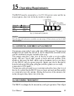
Page 87: ...t have a clear view of the sky in order to receive satellite signals GPS uses line of sight signals to locate and track satellites If the signals are obstructed by dense objects such as aluminum steel or even heavy ice the EKP IV will not operate properly Signals may also be blocked by heated wind screens fiberglass plexiglass and other plastics are nor mally transparent to GPS signals The antenna...

Page 88: ...osure at each end of the strap Hold the EKP IV over the strap on your leg and lower into place Press down a little to be sure the strips are secure If you prefer there are after market mounts available for attachment to the yoke assembly or the seat rail tracks Please contact your dealer for more details on these items NOTE Yoke mounts may not be appropriate for your aircraft Use care to ensure th...

Page 89: ...n MENU 1 sec GPS PAGE ENTER Review the number of satellites in use If zero check that the antenna has a clear view of the sky and that the connections have been made properly If less than four satellites are in use the GPS receiver may have difficulty receiving a fix Try repositioning the antenna A GPS fix requires a minimum of three satellites and a poor Signal Quality on one or more satellites m...

Page 90: ... are likely to encounter Simply disconnecting the EKP IV from power for a moment may solve your problem as well If this does not help try resetting the EKP IV to the factory defaults MENU 1 sec SYSTEM SETUP ENTER FACTORY DEFAULTS ENTER If this does not help you can try one additional memory clear option This is a factory default RAM Clear that should only be tried after all other attempts have bee...

Page 91: ...5 SYSTEM TEST If you have connected your EKP IV according to the instructions and chosen the proper menu selections and are still having problems a RAM Clear will bring the system back to factory default settings Many times this will clear the errors and bring the EKP IV back to operating condition RAM CLEAR can be found in the System Test Menu NOTE The additional tests in the System Test Menu are...

Page 92: ...rted in the slot but it is a damaged Compact Flash the name of the Compact Flash zone and the message Faulty are shown 3 If there is not any Compact Flash inserted in the slot the message not present is shown 4 If there is an User Compact Flash inserted in the slot the message USER CARTRIDGE is shown C CARD Connector Indicates if there is a malfunction in the connector It is used only in productio...

Page 93: ...r example NMEA 0182 instead of NMEA 0183 Check your receiver manual to be sure that you have selected the proper inter face format If the screen is blank you may have a broken connection and no data is being received Use ZOOM IN to stop or continue after pause data displaying ENTER to show data in hex or ASCII mode normal or small and CLEAR to exit ...

Page 94: ...estination together on the screen When this mode is active the cursor is hidden AWOS Automatic Weather Observation Station AZIMUTH Bearing measured clockwise from true or magnetic north BATHYMETRIC LINES Imaginary lines connecting points of equal water depth BEACON An airport rotating beacon white or white and green BISECTOR A straight line that divides an angle into two equal parts BRG BEARING Th...

Page 95: ... day 365 days a year under any weather conditions GQ GEOMETRIC QUALITY A measurement of the geometry of the satellites used to triangulate the posi tion A low GQ is inaccurate and generates a GQ warning Navigation data should be used with caution when the GQ warning appears GREAT CIRCLE Distance measured along the curved surface of the earth Over long distances a Great Circle distance is more accu...

Page 96: ...urse OSGB ORDNANCE SURVEY OF GREAT BRITAIN A Coordinate System describing only Great Brit ain Generally used with GBR36 datum which also describes only Great Britain This Coordinate System cannot be used in any other part of the world POSITION A location that is obtained in real time and expressed as coordinates Sometimes called a fix Also a Waypoint location obtained from a chart or other source ...

Page 97: ...p a Flight Plan WGS84 World Geodetic System 1984 Coordinates System or Datum developed by the Defense Mapping Agency DMA XTE Cross Track Error The perpendicular distance between the present position and the course line Given as a distance right or left of course when facing the destination Displayed in NAV as XTE or on the CDI as a deflection ZOOM IN Shows more detail in a smaller area ZOOM OUT Sh...

Page 98: ...t preceded by a region prefix For example Barrie Executive Airport in Barrie Ontario Canada is NA3 The following pages contain maps and a table of ICAO codes The map of the continental U S contains the 2 character codes that identify the U S K and the area the following number The world map shows the region codes only The ICAO codes in the table are 2 character codes like K2 and similar ICAO codes...

Page 99: ... w a n a C i s k e i Johannesburg Namibia South African Republic Southwest Africa Transkei Venda ICAO CODE NAME FB Botswana FC Brazzaville Congo FD Swaziland FE Central African Republic FG Equatorial Guinea FH Acension St Helena FI Mauritius FJ British Indian Ocean Tr Chagos Archi pelago FIC Cameroon FL Zambia FM Antananarivo Cormors Madagascar Mayotte Island Reunion FN Angola FO Gabon FP Sao Tome...

Page 100: ...Republic LL Israel Jerusalem LM Malta LO Austria LP Azores Madeira Island Portugal Santa Maria Oceanic LQ Bosnia and Herzegovina LR Romania LS Switzerland LT Turkey LX Gibralter LY Yugoslavia LZ Slovakia MB Caicos Islands Turks Islands MD Dominican Republic ICAO CODE NAME MG Guatemala MH Honduras MK Jamaica MM Mexico MN Nicaragua MP Panama MR Costa Rica MS El Salvador MT Haiti MU Cuba MW Cayman Is...

Page 101: ...es VT Thailand VV Vietnam VY Myanmar WA Indonesia WB Brunei Malaysia WI Indonesia WM Malaysia WP Indonesia WR Indonesia WS Singapore YB Australia YD Australia YG Solomon Islands YM Australia YN Nauru South Pacific YP Australia YS Australia YY Papua New Guinea ZB China Peoples Republic of ZG China Peoples Republic of ZH China Peoples Republic of ZK Korea Democratic Peoples Republic of ZL China Peop...

Page 102: ...ination magnetic or true BOD Bearing Origin to Destination BWC Bearing and Distance to Waypoint GGA GPS position time fix quality number of satellites used height of antenna HDOP Horizontal Dilution of Precision differential reference information and age GLL GPS derived Latitude Longitude and time of fix GSA GPS receiver operating mode satellites used in the navigation solution reported by the GGA...

Reviews: