Radar Page
Entegra EX5000
-34-
600-00121-001 Rev 01
4.2 Dedicated Radar Page
You can access the dedicated Radar page by turning the Select knob
to Radar.
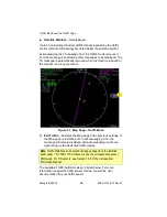
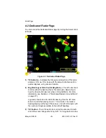
Figure 4.2 Dedicated Radar Page
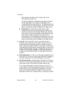
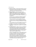
1) Tilt Indicator
—Indicates the tilt angle and direction of the radar
antenna: U for up, D for down with the amount of antenna tilt in
quarter degrees, using decimal notation.
2) Brg (Bearing) or Gain Control (Brg/Gain)
—The left outer knob
controls either the bearing line or the radar gain, depending on
how the
Knob
button was set when in Ground Mode. For more
information, see Section 4.3, "Dedicated Radar in Ground Mode"
on page 37).
In general, this knob will control the bearing. Use the left outer
knob to control the bearing line in 1° increments. The relative
bearing displays at the top of the screen: L for left, R for right, with
the number of degrees relative to the aircraft heading.
3) Tilt Control
—The left inner knob controls the antenna tilt. Each
click of the knob changes the tilt by 0.25°. Turning the knob to the
10
9
7
5
4
1
8
6
3
2
Summary of Contents for Entegra EX5000
Page 1: ...600 00121 001 Rev 01 Entegra EX5000 ...
Page 2: ...Entegra EX5000 600 00121 001 Rev 01 ...
Page 8: ...Entegra EX5000 vi 600 00121 001 Rev 01 This page intentionally left blank ...
Page 20: ...Introduction Entegra EX5000 6 600 00121 001 Rev 01 THIS PAGE INTENTIONALLY LEFT BLANK ...
Page 38: ...Map Page Entegra EX5000 24 600 00121 001 Rev 01 ...
Page 66: ...CMax Chart Pages Optional Entegra EX5000 52 600 00121 001 Rev 01 ...
Page 91: ...600 00121 001 Rev 01 77 Entegra EX5000 THIS PAGE INTENTIONALLY LEFT BLANK ...
Page 92: ...Trip Page Entegra EX5000 78 600 00121 001 Rev 01 ...
Page 96: ...Entegra EX5000 82 600 00121 001 Rev 01 THIS PAGE INTENTIONALLY LEFT BLANK ...
Page 188: ...Reference Entegra EX5000 174 600 00121 001 Rev 01 ...
Page 198: ...Entegra EX5000 184 600 00121 001 Rev 01 This page intentionally left blank ...
Page 199: ......


