


Drive (CDM) Design
T1689 Technical Manual Rev 07
Mechanical Design principles
MV3000 Air Cooled DELTA
Page 80
3.4.3
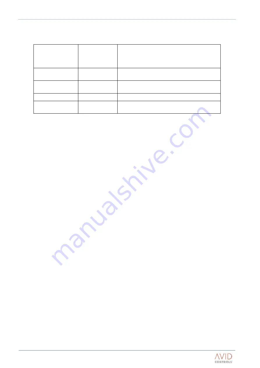
Items To Be Supplied By The PDS Designer / Builder
To complete the power drive system, examples of these are:
Machine (motor or
generator) or
controlled
load/source
For all versions
To include machine monitoring, such as an encoder
Interconnection /
supply cables
For all versions
Transient / over-
voltage protection
For all versions
Earth fault protection For AEM
Supply over-current
protection, etc.
For all versions
Where there is a specific requirement for any of these items to be used with DELTA modules, some guidance
on the design of these components is given in Section 4: PDS Design. The design and specification of these
components is the responsibility of the PDS designer.
3.5
MECHANICAL DESIGN PRINCIPLES
After the selection of the electrical components the mechanical arrangement into an enclosure is required.
3.5.1
The Equipment Must Be Enclosed
The DELTA modules and associated components are usually ‘open type’ products (IP00) for installation into an
enclosure.
•
The front of the DELTA power module is supplied with terminal shrouds. These provide limited
protection for personnel against accidental direct electrical contact;
•
The transistor power modules contain a d.c. link capacitor bank. This capacitor has resistors
fitted to discharge it to below 50V in less than 5 minutes (see specification for the times for
individual modules) after the isolation of the supply;
•
The electrical components on rear and side of the power modules are not shrouded. They will
need to be enclosed to prevent accidental contact.
All wound components (e.g. d.c. link reactor, inter-bridge transformer, input line reactors) must be installed in
a steel enclosure to prevent:
•
Contact of persons against hazardous voltages and temperatures. These are usually supplied as
IP00 (open components);
•
Emission of magnetic and electrical noise.


