


Step 1b (Single Switch):
•
Place the Engine and Switch in their physical locations. (E.g. Rack mount.)
•
Connect power cables, keyboard, monitor, and mouse.
•
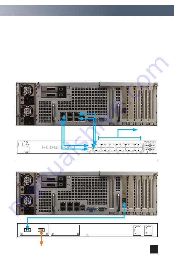
Insert Transceivers and connect network cables: Use Diagram A for 4 x 1 Gb
Ethernet; or, use Diagram B for 1 x 10 Gb Ethernet.
•
Continue with Step 2 (page 5).
Rear view of the
ISIS Engine
P28
27
XFP26
AC
XFP25
DC
Alarm
STACK ID
S25-01-GE-24V
x
x
To Clients
Front view of the Force10 S25 switch
3
Diagram B: Use this diagram for single switch, 10 Gb Ethernet connection.
Diagram A: Use this diagram for single switch, 1 Gb Ethernet connection.
Rear view of the Force10 S25 switch
To 2nd Engine (optional)
Hardware Setup


