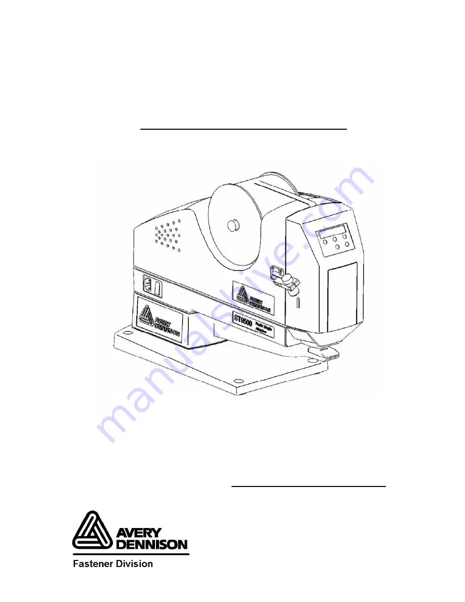
background image


1

ST9

ST9

ST9

ST95

5

5

500™

00™

00™

00™


Plastic Staple

Plastic Staple

Plastic Staple

Plastic Staple

®

®

®

®


Attacher

Attacher

Attacher

Attacher


Item # 15000™


Operator and

Operator and

Operator and

Operator and    
Service Manual

Service Manual

Service Manual

Service Manual

©

©

©

©


Part No. 3-05-0100-01        Rev. 1


Patent(s) Pending 

Summary of Contents for ST9500

Page 1: ...e Plastic Staple Plastic Staple Plastic Staple Attacher Attacher Attacher Attacher Item 15000 Operator and Operator and Operator and Operator and Service Manual Service Manual Service Manual Service M...

Page 2: ...lied or otherwise shall be limited to at Avery s discretion i the replacement of the defective Product at no additional cost to you ii the repair of the defective Product which repair will be made at...

Page 3: ...al was approved for printing Avery Dennison whose policy is one of continuous improvement reserves the right to discontinue models at any time or change specifications or design without notice and wit...

Page 4: ...23 Inspecting the Fastener Cut 24 Chapter 4 Theory of Operation Electric Schematic Block 26 The ST9500TM Cycle 27 Chapter 5 Parts Replacement Removing the Enclosure 30 Replacing the Door Needle Guard...

Page 5: ...or Actuates Abnormally 51 Panel Doesn t Display or Works Abnormally 51 Host Software Application Doesn t Function Properly 52 Fastener Problems 52 Ejection Problems 53 Chapter 7 Routine Maintenance an...

Page 6: ...is connected to a power source Disconnect the power cord before attempting to replace any component Do not operate the ST9500 with the cover removed or make any attempt to defeat the cover interlock s...

Page 7: ...uired to install operate troubleshoot and service the Avery Dennison ST9500TM Plastic Staple Attacher The ST9500 fastens garment size pricing and brand name tags to fabrics by inserting Plastic Staple...

Page 8: ...8 Chapter 2 Installation The chapter describes how to install the ST9500 Unpacking the ST9500 Mounting the ST9500 Setting up the ST9500 for operation...

Page 9: ...3 Remove the power cords select the appropriate cord and discard the unneeded cords For 220 240 VAC UL CSA For 240 VAC CE For 110 VAC UL CSA 4 Visually inspect the ST9500 and the shipping materials f...

Page 10: ...mounting bolts 4 Bolt the ST9500 to the work surface 1 Decide how to mount the ST9500 The ST9500 must be bolted to a stable heavy work surface When shipped from the factory it is set up as shown to t...

Page 11: ...as follows Lower the head by actuating the machine and opening the door before the machine can complete one cycle Manually raise the head of the unit so you can thread the screw into the tapped hole...

Page 12: ...12 4 Plug the foot switch cord into the foot switch receptacle 5 Connect the power cord to an electrical outlet and turn the ST9500 power switch from OFF 0 to ON 1...

Page 13: ...ow to operate the Avery Dennison ST9500 Operating the front panel Adjusting needle spacing Double shot mode and single shot mode switch Loading fasteners Adjusting the fastener cut Inserting a fastene...

Page 14: ...the Cycle Mode The values may be 1 through 10 and C_ If the value is 1 it means the machine will run 1 cycle at a press of foot switch and likewise 2 for 2 cycles per press 3 for 3 cycles per press wh...

Page 15: ...abled Mode to Password Disabled Mode and vice versa In the former mode the user need to enter a valid password before he can change the motor parameters then need press the button 5 SAVE to save it af...

Page 16: ...e settings are not saved to the Flash Memory and therefore if the power fails at this time the settings will not be saved d Press Button 5 to save the parameter settings to the flash memory and the ma...

Page 17: ...17 5 Panel Operation Flow Chart...

Page 18: ...that the Ejector Rods move according to the needles if the Ejector Rods do not move then there might be some friction with the Ejector Rod guide at the top Please use your finger to help it move if n...

Page 19: ...and single shot In double shot mode the machine feeds two pieces of staples at a cycle while in single shot mode the machine feeds one piece of staple at a cycle 4 When the arrow in the picture below...

Page 20: ...asteners on the reel support with the fasteners coming off the top of the reel Check that the reel rotates freely 4 Cut the end of fasteners half way between two rungs 5 Feed the fasteners through the...

Page 21: ...de above the feed wheel 7 Feed the fasteners down behind the feed wheel 8 Turn the feed knob clockwise to advance the fasteners down through the knife block 9 Continue turning the feed knob until the...

Page 22: ...ut after adjustment 2 Feed the fasteners and cut and check if the fasteners are cut properly now at midway 3 Repeat above step 1 and 2 until the fasteners are cut at the correct position Note Please r...

Page 23: ...guards and do not operate the machine without needle guards in place Disconnect power to the machine before replacing needles 2 Press the foot pedal to actuate the machine NOTE The front door is equip...

Page 24: ...24 Inspecting the Fastener Cut 1 Inspect the fastener to see if it is inserted into the fabric correctly 2 Adjust the fastener cut if necessary see page 19...

Page 25: ...25 Chapter 4 Theory of Operation This chapter describes the operating principles of the ST9500 You should read this chapter if you are responsible for troubleshooting and repairing the ST9500...

Page 26: ...of the stepping motor The MCU is also used for panel display The other two MCU are used for network communication and control ST9500 Motor Driver receives instruction from MCU controller and drives th...

Page 27: ...the front panel When the operator presses the footswitch MCU receives a signal as an instruction to run the motor then MCU analyzes the settings that is saved in the RAM and sends signals accordingly...

Page 28: ...the ratchet on the feed wheel advancing one or two depends on setting new fastener s into the cut position When the Head continues to move up all the way to the top it activates the Sensor to give a s...

Page 29: ...ational Check NOTE After repair or reassembly always perform the following operational check 1 Replace the ST9500 enclosure and needle guard WARNING Do not operate the machine without the enclosure an...

Page 30: ...y components Do not operate the ST9500 with the enclosure removed or make WARNING any attempt to defeat the enclosure or interlock switch Moving parts and shock hazard may cause serious personal injur...

Page 31: ...ding the door needle guard 3 Remove the door needle guard WARNING Do not operate the machine with the needle guards removed Needles and moving parts may cause serious personal injury Assembly 1 Positi...

Page 32: ...four screws holding the needle guard 3 Remove the needle guard WARNING Do not operate the machine with the needle guards removed Needles and moving parts may cause serious personal injury Assembly 1...

Page 33: ...scalloped cut in the needle facing the needle lock screw 2 Insert the needle lock screw If necessary rotate the needle so the screw fits into the scalloped cut in the needle 3 Tighten the screw NOTE T...

Page 34: ...e defective Eject Rod together with the black ejector slide Assembly 1 Insert the bottom of the ejector rod into the hole in the eject block 2 Insert the top of the ejector rod into the hole and chann...

Page 35: ...he flat side facing up 2 Position the square hole in the knife over the square projection that drives the knife 3 Position the knife spring over the square projection of knife lever 4 Mount the spring...

Page 36: ...two screws holding the left support plate and then remove the plate 4 Remove the two screws holding the right support plate and then remove the plate 5 Loosen the setscrew on the feed knob and then re...

Page 37: ...plate over the feed wheel shaft Countersunk holes on the plate face out 2 Replace the feed knob spring and tighten the setscrew 3 Reattach the right support plate to the head 4 Reattach the left supp...

Page 38: ...3 Remove the screw on the Feed Stop and remove the Feed Stop 4 Remove the screw on the Sensor assembly and remove the Sensor assembly 5 Remove the two screws on each Slide Plate and then remove the Sl...

Page 39: ...he hole of the crank bushing 5 Replace the two slide plates 6 Replace and adjust the sensor assembly 1 Loosen 2 screws holding sensor 2 Raise sensor to top most position 3 Turn machine to CONTINOUS mo...

Page 40: ...e feed wheel assembly see page 33 4 Remove the four screws holding the feed guide and then remove the feed guide 5 Remove the four screws from the two screw plates while holding the ejector slide Remo...

Page 41: ...lide the shaft out and remove the lever and spring Assembly 1 Insert the knife lever shaft through the right side of the head the knife lever and spring 2 Hook the spring to the bottom of the knife le...

Page 42: ...aligned by inserting a tool into the alignment hole in the left side of the head see page 37 Disassembly 1 Unplug the unit 2 Remove the feed wheel assembly see page 31 3 Remove the feed guide and the...

Page 43: ...when the head is off the machine 6 Replace the head by aligning the top of the ejector slide with the top of the slide s guide track 7 Make sure the crank arm pin is at top dead center then insert the...

Page 44: ...4 Disconnect the connectors 5 Remove the three screws holding the circuit board 6 Remove the circuit board assembly the upper layer is MCU controller while the lower layer is Motor Driver Assembly 1...

Page 45: ...180 degrees and hang it on the thumbscrew 4 Remove the circuit board see page 46 5 Remove the two ground screws and take out the Capacitor Assembly 1 Position the Capacitor and tighten the screws 2 Po...

Page 46: ...emove the ground wire from the motor housing 5 Remove the four bolts from the bottom of the frame that secure the mount 6 Remove the Motor Coupling and Crank as one assembly 7 Remove the four bolts ho...

Page 47: ...k arm into the bushing on the back of the head 6 Press the collar into the hole in the frame 7 Replace and tighten the four screws that hold the motor coupling and crank arm assembly to the mount 8 Co...

Page 48: ...ee page 45 3 Remove the screws holding the crank arm 4 Remove the crank arm Assembly 1 Place the Key in the slot of crank arm 2 Place the crank arm on the face of the coupling aligning the pin on the...

Page 49: ...coupling holding the motor shaft 5 Remove the coupling Assembly 1 Place the key of the coupling in the slot of the motor shaft 2 Mount the coupling and tighten the screw holding the motor shaft 3 Pla...

Page 50: ...or reassembly always perform the following operational check 1 Replace the ST9500 enclosure and needle guard Do not operate the machine with the enclosure and needle guards WARNING removed Needles and...

Page 51: ...ensor Position of sensor is not proper Check the sensor and make sure the screws do not loose and the position of sensor bracket is correct so that the Head always stops at the top Fabric are too thic...

Page 52: ...ms Symptom Probable cause Action Bad fastener cut Back out and re cut fastener end Then re feed fasteners Not feeding one fastener pitch Adjust feed screw Feed jam of fasteners Contamination of the fe...

Page 53: ...ble cause Action Fastener not ejecting Bent ejector rods Replace rods Ejector rods bending Ejector slide not installed Readjust slide correctly Knife too tight Check that knife can move freely Broken...

Page 54: ...nce You should blow out the Plastic Staple path daily with compressed air to remove dust and any contaminants This is the only daily maintenance required CAUTION Do not use any type of lubricant on th...

Page 55: ...mately every six months or one million cycles The following areas should be lubricated with light grease 1 way bearing Sliding surfaces on Ejector Slider Crank Slot on Knife Block Sliding surfaces on...

Page 56: ...56 Routine Maintenance and Lubrication The following areas should be lubricated with light sewing machine oil...

Page 57: ...To order replacement parts contact your local Fastener Division sales office A full list of worldwide contacts is included in the next chapter You will need the following information The Avery Dennis...

Page 58: ...58 Whole Machine Exploded Illustration...

Page 59: ...1 13 140002010501 Screw Hexagon Socket Half Round Head Stainless Steel 4X10 4 14 140012012601 Lock Washer D4 4 15 140012000302 Washer D4 4 16 3 06 0023 01 Assy Stop Feed 1 17 3 06 0024 01 Assy switch...

Page 60: ...60 Base Assembly and Body Assembly Exploded Illustration...

Page 61: ...6 140012008101 Lock Washer Black D6 8 57 140012008601 Washer Black D6 4 58 3 05 0094 01 Thumbscrew 1 59 140012015801 Washer Black D5 1 60 3 06 0004 01 Assy Receptacle Power Cord 1 61 130028003201 Fuse...

Page 62: ...62 Motor Assembly Exploded Illustration...

Page 63: ...1 94 130901001401 Tie Self Clinching Nylon 1 95 3 06 0008 01 Assy Motor 1 96 3 05 0010 01 Ring Offset 1 97 DT0222 001 Pin 1 Offset Ring 1 98 DT0224 001 Bushing Square 1 99 130305012301 Step Motor 1 10...

Page 64: ...1 122 ST0324 001 Shade Lamp 1 123 140001057101 Screw Hexagon Socket Cup Head Stainless Steel 2X5 2 124 140011003701 Nut Hexagon M3 1 125 140001000302 Screw Hexagon Socket Cup Head Black 3X10 1 126 14...

Page 65: ...65 Head Subassembly and Knife Lever Assembly Exploded Illustration...

Page 66: ...DT0116 001 Shaft Knife Lever 2 159 DT0106 001 Guide Knife Lever 2 160 110017000101 C Ring Shaft 4 161 140003009001 Screw Hexagon Socket Countersunk Head Black 4X8 2 162 3 06 0015 01 Assy Knife Lever...

Page 67: ...67 Base Knife Assembly Exploded Illustration...

Page 68: ...01 Block Guide Long 1 190 3 05 0068 01 Spring adjust needle space 1 191 140001000802 Screw Hexagon Socket Cup Head Black 3X6 4 192 140004000702 Trip Bolt Hexagon Socket Head Black 3X5 1 193 1400010012...

Page 69: ...69 Left and Right Needle Holder Assembly Exploded Illustration...

Page 70: ...8 3 219 140001000302 Screw Hexagon Socket Cup Head Black 3X10 2 220 140012007901 Lock Washer Black D3 6 221 140012012201 Washer Black D3 2 222 3 06 0018 01 Assy Holder Needle Right 1 223 3 05 0031 01...

Page 71: ...71 Guide Bar Assy Feed Assy and Feed Lever Assy Exploded Illustration...

Page 72: ...0042 01 Handle Feed 1 257 DT0163 001 Post Tension Spring 1 258 DT0137 001 Collar Feed 1 259 DT0140 001 Key 1 260 DT0145 001 Plate Support Right 1 261 110013021701 Roller bearing one way 1 262 11001603...

Page 73: ...nce Staple 1 296 140001001201 Screw Hexagon Socket Cup Head Black 4X10 4 297 140012012101 Washer Black D4 4 298 140012008001 Lock Washer Black D4 4 299 140001001002 Screw Hexagon Socket Cup Head Black...

Page 74: ...74 Switch Power Supply Assy and Driver Assy Exploded Illustration...

Page 75: ...ck Washer Black D4 1 329 140001057801 Screw Hexagon Socket Cup Head Black 5X12 2 330 140012015801 Washer Black D5 2 331 140012010601 Lock Washer Black D5 2 333 3 05 0052 01 Holder Driver 1 334 3 06 00...

Page 76: ...oard Wire 1 355 DT0018 001 Spring Front Door 2 356 3 05 0088 01 Cover Screw 9 357 3 05 0085 01 Shaft Cover 3 358 140002010501 Screw Hexagon Socket Half Round Head Stainless Steel 4X10 6 359 1400120126...

Page 77: ...77 Door Enclosure Assy Exploded Illustration...

Page 78: ...Washer 3X12 4 377 3 06 0030 01 Assy Panel 1 378 3 05 0061 01 Board Support 1 379 3 05 0090 01 Cover PCB 1 380 140001001002 Screw Hexagon Socket Cup Head Black 3X8 4 381 140012012201 Washer Black D3 4...

Page 79: ...2 81 8864 4101 Email fastener mexico averydennison com BRAZIL Avery Dennison do Brasil Ltda Rua Francisco Foga 225 CP 18 CEP 13280 000 Vinhedo SP Brasil Tel 55 19 3876 7696 0800 7010076 Fax 55 19 3876...

Page 80: ...Phone 81 42 526 7310 Fax 81 42 526 7315 Email info_fap ap averydennison com JAPAN OSAKA Avery Dennison Overseas Corporation Shin Osaka Ikushima Bldg 7F 5 1 3 Miyahara Yodogawa ku Osaka City Osaka 532...

Reviews: