Any mounting orientation may be used for the HU1 holding
unit.
The compressed air connection has an assembly screw.
O
Do not remove this screw until shortly before
connecting the compressed air supply.
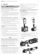
Mounting the HU1 holding unit on an ISO
cylinder
To mount the HU1 holding unit as an individual component
on an ISO cylinder, proceed as follows:
1.
Slide the holding cartridge (
1
) into the mounting flange
(
3
).
2.
Remove the nut (
7
) from the cylinder piston rod to
avoid damaging the scraper (
6
).
3.
Slide the holding cartridge (
1
) and mounting flange (
3
)
together onto the cylinder piston rod.
NOTICE
Danger of piston rod slipping and destroying the
mechanical clamping jaws!
Transverse loads on the piston rod will destroy the
clamping jaws.
O
Ensure that the piston rod is only loaded in the
direction of movement.
Extensive wear on the piston rod and clamping jaws!
If the locked piston rod is moved against the effective
clamping forces, this will result in wear on the piston
rod and the clamping jaws.
O
Ensure that the static holding force of the HU1
holding unit is not exceeded at any time. Otherwise,
this may lead to unexpected movement of the piston
rod.
1.
1.
1
1
3
3
ISO 15552
ISO 6432
4. ISO 15552 cylinders:
Fix the HU1 holding unit to the
cylinder using the four mounting screws. Observe the
stated tightening torques (see “9 Technische Daten”).
5. ISO 6432 cylinders:
Completely screw the HU1 holding
unit onto the cylinder thread and align it.
6.
Tighten the cylinder lock nut (
7
) against the holding
unit. Observe the stated tightening torques (see “9
Technische Daten”).
3.
2.
2.
3.
1
1
7
7
3
3
6
6
ISO 15552
ISO 6432
ISO 15552
7
ISO 6432
AVENTICS
| HU1 |
R412022330–BAL–001–AB
| English
8


