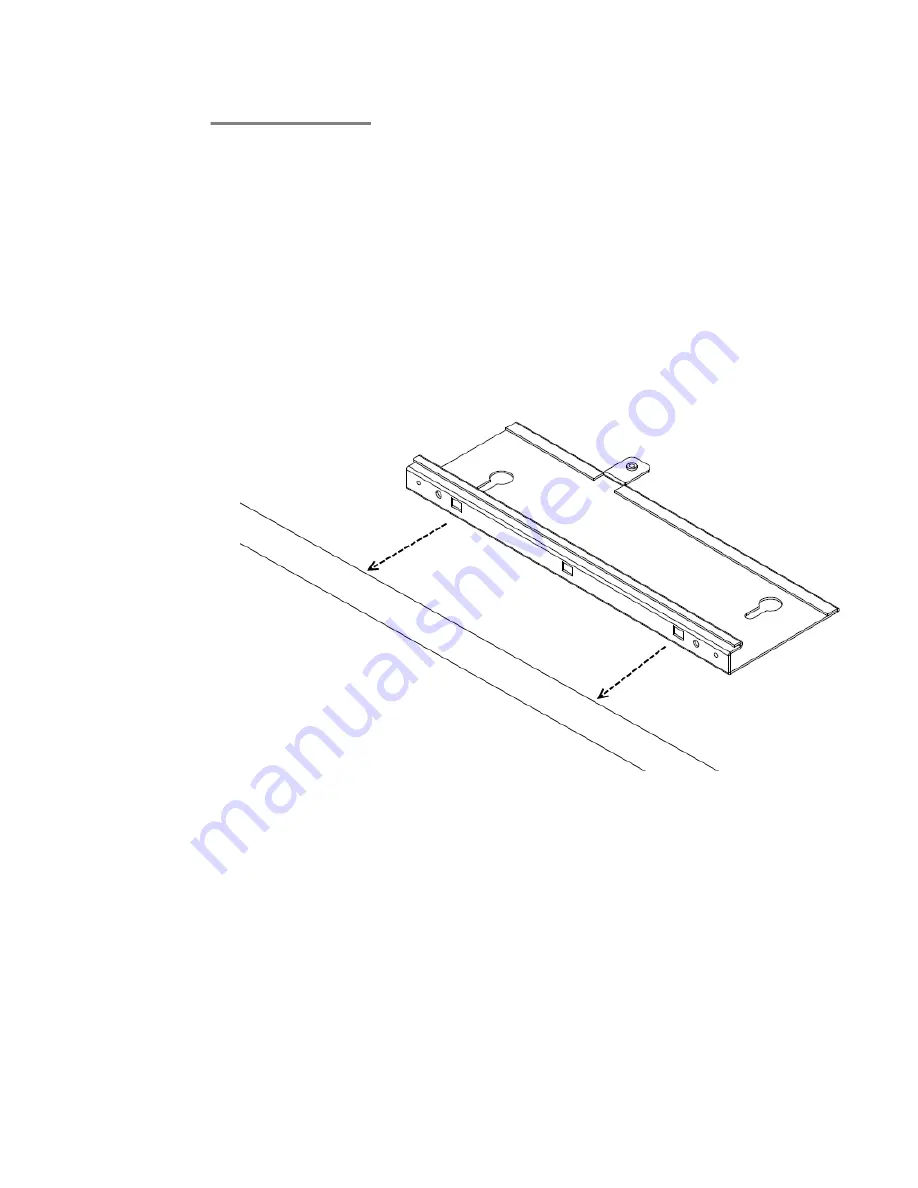
1. Secure a safe work environment. Obtain a ladder that allows easy access to the
ceiling grid system.
2. Identify an appropriate location on the ceiling grid where the ceiling T-bars are safely
accessible and where the ceiling tiles can be temporarily elevated and cleared away
from the work area. The adaptor bracket assembly is intended for use with the thin
section grid runners, not the thicker section runners used to cross large spans. To
provide access for hands and tools, use a pair of pencils or sticks to hold up the
ceiling tiles out of the grid. Doing this provides easy access for securing the bracket
to the grid.
3. Mount the larger bracket to the grid. While installing, pay attention to the width of
the grid strip in order to ascertain the appropriate orientation for the smaller bracket
which is installed next.
4. Mount the interlocking small bracket to the large bracket and clamp the two pieces
together on the grid. The smaller bracket has tabs formed into it which engage slots
in the larger tab. This allows the two parts to slide together and lock to one another.
When this is done, the two brackets effectively clamp themselves around the ceiling
grid. When the two halves of the bracket are correctly slid together, the captive
fastener in the small bracket should engage threads provided in the larger bracket.
Use a screwdriver to screw down the captive fastener. Securing the two brackets
in this manner is essential to prevent them from disengaging from one another.
Tighten the captive fastener screw securely.
Access Point 8120 installation
16 Avaya WLAN 8100 Installation–AP 8120
August 20, 2010
Summary of Contents for WLAN 8100 Series
Page 1: ...Avaya WLAN 8100 Installation AP 8120 1 0 0 0 NN47251 302 01 01 August 20 2010 ...
Page 4: ...4 Avaya WLAN 8100 Installation AP 8120 August 20 2010 ...
Page 20: ...Installation tools and utilities 20 Avaya WLAN 8100 Installation AP 8120 August 20 2010 ...
Page 22: ...Access Point Troubleshooting 22 Avaya WLAN 8100 Installation AP 8120 August 20 2010 ...


