


28
5.
OPERATION
5.1
Raise And Lower Lift
Prevent serious injury or death.
Before operating lift, all personnel interacting with lift must read, understand
and follow instructions and safety warnings in this manual.
Personnel must maintain a safe operating distance of at least 36” any time
lift is operated.
Adjusting safety relief valve may result in premature motor failure.
Do not adjust safety relief valve.
Raising loads exceeding rated capacity of lift may result in excessive wear and
damage to lift.
For lifts supplied with throw-over bridges, make sure bridges are in the stored
(raised) position prior to raising or lowering the lift, and when backing up trucks
for loading/unloading - to ensure that the bridges will clear all possible
obstructions and contact with a moving truck.
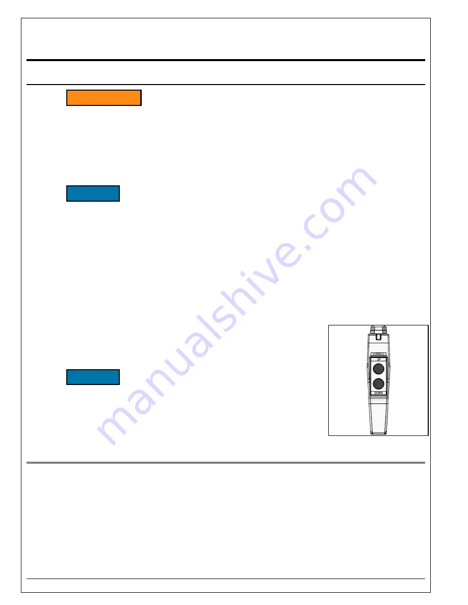
1. Verify all personnel are clear of lift.
2.
Press “UP” button to raise lift. Release button when lift reaches desired
position.
Do not operate lift on relief for more than a
few seconds. When on relief, valve will make a squealing
sound.
3. Press "DOWN" button to lower lift. Release button when lift reaches
desired position.
5.2
Raise And Lower Bridge (hydraulic)
If your lift has a hydraulically operated throw over bridge (TOB), it is equipped with UP/DOWN buttons and
a FLOAT switch. The FLOAT switch must be set to
“LOCK” for the UP/DOWN buttons to work. The
UP/DOWN operate just as the lift UP/DOWN. The FLOAT switch is to be used when the bridge is resting
on the truck bed. The “FLOAT” mode allows the bridge to float up or down with the truck.
This prevents damage to the equipment when loads are being moved across the bridge.
Note: Bridges that hang below 45 degrees are in violation of ANSI Standard MH29.1-2012 paragraph
4.12.2 which states “When a hinged bridge is in its fully lowered position and not resting on a truck bed or
landing, it should hang down at an angle not to exceed approximately 45 degrees from horizontal.…”
Autoquip
’s standard is to allow 20° of drop below horizontal.
i
WARNING
NOTICE
NOTICE
Summary of Contents for PLTC-58120
Page 13: ...13 1 DECAL_CAPACITY 2 36430050 3 36401487 4 36401560 5 06100010...
Page 14: ...14 6 36403225 7 36400265 8 36400257 9 36403720 10 36433670...
Page 17: ...17 PLT Pit Detail See Pit Installation Notes...
Page 19: ...19 Lifting and Installation...
Page 22: ...22 4 6 Bridge Lifting Chain Installation Steel Bridge...
Page 23: ...23 4 7 Bridge Lifting Chain Installation Aluminum Bridge...
Page 24: ...24 4 8 Bridge Winch Installation Steel Bridge...
Page 25: ...25 4 9 Bridge Winch Installation Aluminum Bridge...
Page 26: ...26 4 10 Pit Modification Installation for Mechanical Wheel Chock...
Page 30: ...30 Figure 6 1...
Page 35: ...35 Figure 6 3 Cylinder Seals...
Page 39: ...39 Electric Schematic 5HP 3Ph Continuous Running Vertical Power Unit...
Page 40: ...40 Electric Schematic 5HP 1Ph 230V Vertical Power Unit...
Page 41: ...41 Electric Schematic 3HP 1Ph 115V Vertical Power Unit...
Page 42: ...42 Hydraulic Schematic Contractor Power Unit...
Page 43: ...43 Hydraulic Schematic Vertical Power Unit...
Page 44: ...44 Hydraulic Schematic Continuous Running Vertical Power Unit...
Page 45: ...45 Push Button Wiring Diagram...
Page 46: ...46 Guarded Foot Switch Wiring Diagram...
Page 47: ...47 Guarded Foot Switch Assembly...
Page 48: ...48 Optional Limit Switch Mounting Diagram PLTC 6050 to 6060...
Page 49: ...49 Optional Limit Switch Mounting Diagram PLTC 6070 to 58150...
Page 54: ...54 7 PARTS LISTS Contractor Power Unit...
Page 55: ...55 Vertical Power Unit...


