


2-10
2 Safety precautions
2
2.3-4 Machine
operator
Only trained or instructed persons are allowed to operate the equipment.
The machine operator is an individual that has enough training and/or knowledge to
run the equipment in the correct way.
2.3-5 Fork lift driver
Fork lift driver should be certified according to local regulations.
The fork lift driver´s role during installation is:
•
to unload transport vehicle
•
to plan and transport the machine or machine parts within the plant in a safe
and smooth way
•
to assist when assembling Autopack equipment
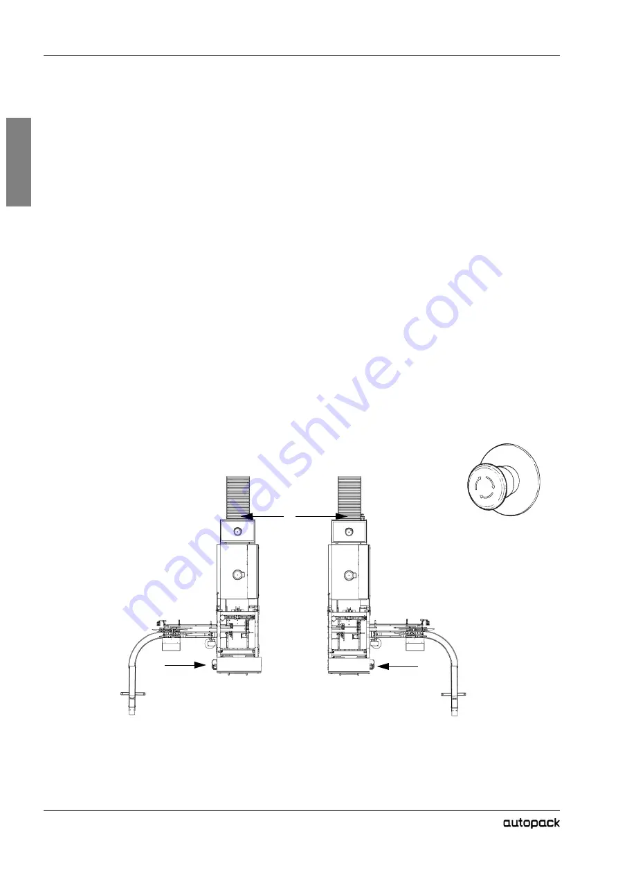
2.4 Emergency stop
In case of danger to people or risk of damage to the machine, one of the four
Emergency stop
buttons must immediately be pushed.
In order to stop the machine immediately in an emergency situation, you must
know the exact location of the Emergency stop buttons
.
Emergency stop
must only be used in case of danger to people or machine. To
stop production in the normal way, see the
Stop
section in chapter operation
instructions.
Note!
Emergency stops do not disconnect the electrical supply to the machine.
Location Emergency stop buttons
1 E- Stop - Wrapper Electrical Cabinet
2 E- Stop - Cooling fan unit
1
1
2
Summary of Contents for 45TLW20VL
Page 4: ...1 2 1 Introduction 1 This page intentionally left blank...
Page 6: ...1 4 1 Introduction 1 This page intentionally left blank...
Page 11: ...2 1 2 2 Safety precautions...
Page 12: ...2 2 2 Safety precautions 2 This page intentionally left blank...
Page 14: ...2 4 2 Safety precautions 2 This page intentionally left blank...
Page 26: ...2 16 2 Safety precautions 2 This page intentionally left blank...
Page 27: ...3 1 3 3 Installation...
Page 28: ...3 2 3 Installation 3 This page intentionally left blank...
Page 30: ...3 4 3 Installation 3 This page intentionally left blank...
Page 37: ...4 1 4 4 Maintenance...
Page 38: ...4 2 4 Maintenace 4 This page intentionally left blank...
Page 51: ...4 Maintenance 4 15 4 Figure 01 Example of Function Code Data Changing Procedure...
Page 55: ...4 Maintenance 4 19 4 To move cylinder unlock screw 4...
Page 56: ...4 20 4 Maintenace 4...
Page 57: ...4 Maintenance 4 21 4 4 7 Knife Replacement...
Page 58: ...4 22 4 Maintenace 4 4 8 Welding Bar Heater Assembly Replacement...
Page 66: ...4 30 4 Maintenace 4...
Page 67: ...4 Maintenance 4 31 4...
Page 68: ...4 32 4 Maintenace 4...
Page 69: ...4 Maintenance 4 33 4...
Page 70: ...4 34 4 Maintenace 4...
Page 71: ...5 1 5 5 Electrical Components...
Page 72: ...5 2 5 Electrical Components 5 This page intentionally left blank...
Page 74: ...5 4 5 Electrical Components 5 This page intentionally left blank...
Page 79: ...5 Electrical Components 5 9 5 5 2 Electrical system description 5 2 1 Safety system...
Page 80: ...5 10 5 Electrical Components 5 This page intentionally left blank...
Page 81: ...5 Electrical Components 5 11 5 This page intentionally left blank...
Page 86: ...5 16 5 Electrical Components 5 5 4 Electrical Component 5 4 1 Wrapper Top view Side view...
Page 91: ...6 1 6 6 Spare Parts...
Page 92: ...This page intentionally left blank...
Page 94: ...6 4 Assembly drawing WEL13261 Graphic ID WEL13261 eps Parent Drw WEL13261 dwg KNIFE ASSEMBLY...
Page 98: ...6 8 Assembly drawing SHRINK TUNNEL SPARE PARTS...
Page 100: ...6 10 Assembly drawing Electrical Spear parts Wrapper...
Page 103: ...6 13 Assembly drawing This page intentionally left blank...
Page 104: ...6 14 Assembly drawing Electrical Spear parts Tunnel...
Page 107: ...7 1 7 7 Human Machine Interface...
Page 108: ...7 2 7 HMI operation 7 This page intentionally left blank...
Page 110: ...7 4 7 HMI operation 7 This page intentionally left blank...
Page 119: ...8 1 8 8 Diagrams Drawings...
Page 120: ...8 2 8 Diagrams Checks 8 This page intentionally left blank...
Page 121: ...This page intentionally left blank...
Page 122: ...This page intentionally left blank...