background image

33

Problem

Solution

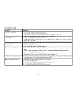
Picture is distorted.

•  The disc might be damaged, try another disc.
•  It is normal for some distortion to appear during forward or reverse scan.

No forward or reverse scan.

•  Some discs have sections that prohibit rapid scanning or title and chapter skip.
•   If you try to skip through the warning information and credits at the beginning of a movie, you won’t be 

able to. This part of the movie is often programmed to prohibit skipping through it.

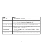
HDMI/MHL input not working for the 
HDMI/MHL enabled device.

•  May require a special HDMI/MHL adapter. Contact your HDMI/MHL device supplier for the adapter.

Game source does not work

•  The Game source can not be selected (grayed out) if the MVGP1 Game Module is not installed. Make sure 

the MVGP1 Game Module is installed and plugged in.

DTV source does not work

•  The DTV source can not be selected (grayed out) if the DTV Module is not installed. Make sure the DTV is 

installed and plugged in.

AV source does not work

•  The AV source cannot be selected (grayed out). The DTV module is installed. This input is shared with DTV 

input.


Summary of Contents for VODEXL10 A

Page 1: ...VODEXL10 10 1 OVERHEAD LED BACKLIT LCD MONITOR WITH DVD PLAYER INSTALLATION GUIDE ...

Page 2: ...NG 7 GENERAL VEHICLE INSTALLATION APPROACH 8 VEHICLE PREPARATION 9 CONNECTING THE DOME LIGHTS 10 INSTALLING THE MOUNTING BRACKET 12 INSTALLING THE VODEXL10 VIDEO SYSTEM WIRING DIAGRAM 13 INSTALLING THE VODEXL10 VIDEO SYSTEM MOUNTING THE UNIT 14 APPENDIX A REMOVING THE TRIM RING SNAP ON SHROUD AND SCREEN COVER 15 APPENDIX B INSTALLING THE OPTIONAL THICK TRIM RING 16 APPENDIX C INSTALLING THE OPTION...

Page 3: ...t Lock the LCD screen in fully closed position when not in use t Before putting on headphones always adjust the volume setting to OFF or lowest position t Remember to leave the dome light switch in the off or auto position when the vehicle is unattended as the dome lights if left on can drain the vehicle battery t Do not put pressure on the screen t Caution children to avoid touching or scratching...

Page 4: ...CHANNEL HEADPHONES USE THE DOWN KEY ON THE REMOTE CONTROL TO SELECT M2 AND PRESS OK TO SET THE MONITOR TO M2 MODE TO REMAIN IN THE M1 MODE PRESS OK M1 M2 3 Selecting a Monitor Code M1 or M2 1 Power ON the unit and wait until M1 or M2 appears on the OSD M1 or M2 will appear on the screen for 4 5 seconds 2 Press the System Menu button on the remote control to display the system menu to change the mo...

Page 5: ...amage to vehicle roof or other components wiring etc 3 Remote Control w Battery P N 136 5326 1 pc 4 Mounting Bracket P N 108 4088 1 pc 5 6 Pin Power Dome Light Harness P N 112 4254 1 pc 6 2 Pin Power Harness P N 112 3881 1 pc 7 12 Pin AV input Harness P N 112 4094 1 pc 8 5 Pin AV output Harness P N 112 4260 1 pc 9 Trim Ring Shale P N 172 0198 1 pc Pewter P N 172 0199 1 pc Black P N 172 0200 1 pc 1...

Page 6: ...Masking Tape 8 Multimeter to verify 12 volt DC and continuity Do not use a test light or logic probe 9 Marker pen to mark headliner to mark trim ring if used 10 Scribe to mark trim ring if used 11 Miscellaneous t Electrical Connectors to connect to vehicle power source requirements will vary from vehicle to vehicle t DVD Movie to verify system operation after installation Preparation Place the uni...

Page 7: ...n of the shroud in the area of the double sided tape to ensure that the tape adheres 5 Locate the Slide Knob 3 in the hardware package and press it onto the dome light switch 4 on the side of the DVD player Installing the Screen Cover 1 Open the LCD screen 2 Hook the two tabs A as shown on the bottom edge of the screen 3 Carefully snap the opposite side over the hinge NOTE If the wrong color Shrou...

Page 8: ... of a headliner that is not flat see Appendix B of this manual NOTE The trim rings supplied with this unit are not designed to be trimmed INSTALLING THE TRIM RING Installing the Trim Ring 1 Turn the DVD Player over on a surface with protective covering to prevent scratches 2 Place the trim ring onto the DVD Player Align the pins on the trim ring with the holes in the metal chassis plate 3 Locate t...

Page 9: ... wiring instructions for the individual components and accessory options being installed Be sure that all wiring is protected from sharp edges and is routed in such a manner that wiring is not pinched when all components and interior trim are fully installed Be sure to leave enough slack in the wiring at each component to allow working room Avoid routing wiring near or over airbag wiring or airbag...

Page 10: ...nstalled The monitor should be located in such a manner that it can be comfortably viewed by rear seat passengers NOTE Never install the monitor in a place within the driver s view This is not only dangerous but it is also illegal in many states 4 Once the mounting location of the monitor has been determined additional preparation work may be necessary depending on the vehicle structure and instal...

Page 11: ...he Purple Brown Lamp Auto wire to the vehicle s switched wire Then connect the Red Black Lamp ON wire to a fused constant 12 volt source and the Black Red Lamp Common wire to a good ground Positive switched systems are commonly found on Ford vehicles For negative switched systems connect the Purple Brown Lamp Auto wire to the vehicle s switched wire Then connect the Red Black Lamp On wire to a goo...

Page 12: ...mputer Red Black Lamp ON Black Red Lamp Common Purple Brown Lamp Auto Positive Switched Dome Lighting Fused Factory Dome Light Circuit To 3 pin connector To constant Factory Door Ajar Switch or Body Control Computer Red Black Lamp on Black Red Lamp common Purple Brown Lamp Auto To constant 12 VDC 12 VDC Negative Switched Dome Lighting Fused ...

Page 13: ...the bracket When cutting the headliner make sure no wires above the headliner are cut 3 While holding the Mounting Bracket in place install the 4 8 x 3 8 Self Drilling Screws CAUTION Be sure that the Self Drilling Screws do not pierce the outer roof skin when fully fastened to the Roof Cross Member Self Drilling Screws Mounting Bracket Headliner Roof Cross Member Roof 4 x Self Drilling Screws 8 x ...

Page 14: ...system by tapping into an accessory hot line and a good ground NOTE This connection must be fused at the vehicle connection point 3 Connect the 2 pin connector on the Power Harness to the 2 pin connector on the Power Dome Light Harness Plug the Power Dome Light harness into the unit in the location shown 4 If connecting to an external source plug in the 12 pin AV Input Harness P N 112 4094 in the ...

Page 15: ...ions 2 Attach the VODEXL10 unit to the mounting bracket using four M5 screws CAUTION The M5 screws are supplied in three different lengths 10mm 20mm and 40mm to facilitate proper installation Use extreme caution when using these screws to avoid damage to vehicle roof or other components wiring etc CAUTION Do not trap any wiring between the bracket and the unit VODEXL10 NOTE Do not over torque or o...

Page 16: ...en the Housing and Screen Back Cover 2 Press the pry tool to release the Screen Back Cover 3 While lifting the Screen Back Cover slide the pry tool around to the attaching areas and press the pry tool to release the Screen Back Cover 4 Remove the Screen Back Cover and discard APPENDIX A REMOVING THE TRIM RING SNAP ON SHROUD AND SCREEN COVER This section is intended for situations where the color o...

Page 17: ... cut completely through the plastic the cut only need be over 50 of the wall thickness of the plastic By bending the cut back and forth several times the plastic will break cleanly at the cut 4 Check the fit of the trimmed console and make any minor adjustments necessary This section covers only special installation considerations for the optional thick trim ring installation If the video monitor ...

Page 18: ...are kit 5 Using a screwdriver install the two screws into the two locations shown NOTE Use caution tightening screws as the threads may strip in the DVD Player 6 Insert the 8 pin connector of the MVGP1 Game Module harness into the location shown 7 Verify Game Module and Game Controllers function properly refer to Owner s Manual This section is intended as an installation guide to connect the MVGP1...

Page 19: ...is inserted in the correct position NOTE The DVD system only plays digital video discs audio CDs and MP3s t Both the unit and the disc are coded by region If the regional codes don t match the disc can t be played This DVD player is set to Region 1 t Check if batteries are installed correctly t Make sure that the headphone batteries are fresh t Check if Power Button lights up when pressed If Power...

Page 20: ...nel t Reposition the VODEXL10 Wireless FM antenna for better reception t Install an FMDIRB ordered separately t Check if the battery is installed correctly t Make sure that the remote control battery is fresh t The remote control is a dual function remote control make sure M1 M2 is selected correctly t A special adapter is required to connect a smartphone to the HDMI input Contact the smartphone s...

Page 21: ...NOTES 20 ...

Page 22: ...128 9230a 2013 AUDIOVOX 150 Marcus Blvd Hauppauge NY 11788 www audiovoxproducts com ...

Page 23: ...VODEXL10 10 1 OVERHEAD LED BACKLIT LCD MONITOR WITH DVD PLAYER S PUSH OPERATION MANUAL ...

Page 24: ...ystem Menu Settings and Adjustments 17 FM Modulator 18 Default DVD 19 Screen Mode 19 Monitor Mode 20 IR Transmitter 20 Language 21 Factory Setting 21 DVD Setup Menu Setting and Adjustments 22 Using the Setup Menu 22 Language Setup 22 DVD Subtitle Setup 23 DVD Audio Setup 23 DVD TV Display 24 DVD TV Type 24 DVD Rating Setup 25 Change Password 25 Load Factory 26 Screen Saver 26 Playing DVDS 27 Playi...

Page 25: ...ference in a residential installation Reorient or relocate the receiving antenna Increase the separation between the equipment and receiver Connect the equipment into an outlet on a circuit different from that to which the receiver is connected Consult the dealer or an experienced radio TV technician for help FCC Caution Any change or modifications not expressly approved by the party responsible f...

Page 26: ...on or navigation If the LCD panel or video monitor is used for television reception video or DVD play the LCD panel or video monitor must be installed so that these features will only function when the vehicle is in park or when the vehicle s parking brake is applied An LCD panel or video monitor used for television reception video or DVD play that operates when the vehicle is in gear or when the ...

Page 27: ...justments can be accomplished using the remote control while seat belts remain fastened Enjoy your AUDIOVOX entertainment system but remember the safety of all passengers remains the number one priority FEATURES 10 1 TFT Thin Film Transistor Active Matrix LCD Liquid Crystal Display Monitor LED Backlighting Built in DVD Player Auto On With Disc Insertion HDMI MHL Inputs OSD On Screen Display for Co...

Page 28: ...ght the desired source Press the Source Select button to access the desired source 6 STOP Button Press the STOP button once Stops playback Pressing the PLAY button again will resume normal playback from where movie was stopped Press the STOP button twice and then press the PLAY button to start playback from the beginning of the DVD 7 EJECT Button This button is used for ejecting a disc from the di...

Page 29: ...ice that contains a battery Note The USB input supplies up to 1 Amp of charging current Devices such as tablets may require more than 1 Amp of charging current and it is recommended to connect the device to a vehicle power outlet for full charging capabilities When the unit is in DVD USB mode 1 Amp charging is not available 4 HDMI MHL 1 INPUT For connection of devices with HDMI MHL outputs Note Re...

Page 30: ...ppear on the screen for 4 5 seconds 2 Press the System Menu button on the remote control to display the System Menu to change the monitor code from M1 to M2 3 Use the W or X cursor buttons to select the Setting sub menu 4 Use the S or T cursor buttons to select the Monitor Mode sub menu 5 Use the W or X cursor buttons to select the desired Monitor Mode M1 or M2 6 Press OK to confirm the setting Th...

Page 31: ...to use the remote control Battery Replacement 1 Remove the battery holder 2 Insert one CR2025 battery into the battery holder Be sure to observe the correct polarity 3 Align the battery holder with the remote control and insert Push it in until the holder clicks CR2025 REMOTE CONTROL FUNCTIONS 1 3 2 4 5 6 7 8 9 10 12 14 11 13 15 16 17 18 19 20 21 22 23 24 25 26 27 28 29 30 31 32 ...

Page 32: ... control of the unit in M2 mode 4 SCAN BACKWARD Press to search in a backward direction Press repeatedly to change the search speed from 2 4 8 16 times and normal speed 5 SCAN FORWARD Press to search in a forward direction Press repeatedly to change the search speed from 2 4 8 16 times and normal speed 6 TV Mode Select Switches certain function keys on the remote control for monitor functions 7 PR...

Page 33: ...to execute a selected setting or menu option 14 SETUP Allows the user to access the Setup Menu when the unit is in DVD mode Use the ST W or X cursor buttons to select options such as language video rating Misc 15 REPEAT Allows the user to repeat a selected title chapter or track 16 A B REPEAT Allows user to repeat the playback from point A to point B Press A B button On Screen Display DVD player O...

Page 34: ...play and select audio language in DVD mode Each time this button is pressed the language changes Note The available languages vary from disc to disc 21 FM MODULATOR CHANNEL SELECT C The unit has a 100 channel built in wireless FM Modulator The FM Modulator can be set from 88 1 MHz to 107 9 MHz in 0 2 MHz steps i e 88 1 88 3 88 5 88 9 90 1 etc Pressing the C button will display the FM Modulator fre...

Page 35: ...iously set level 27 DISC MENU Allows the user to access the disc s menu mode 28 STOP Press to stop playback Playback will resume from the point it is stopped Press twice to stop playback fully Playback will resume from the beginning of the disc 29 PAUSE II Press to pause playback 30 DVD Source No function on this model 31 DVD Mode Select Button Switches certain function keys on the remote control ...

Page 36: ...the system is in use 3 Press the power button on the unit or the remote control to turn the system on and off When in use the internal backlighting will illuminate the controls 4 After the unit has been turned on and is displaying a picture adjust the viewing angle by pivoting the screen to optimize the picture quality 5 Remember to turn the unit off and pivot the LCD screen to the locked position...

Page 37: ...Interleaved files Note Some AVI files may not be compatible with the system maximum video resolution is 720 x 480 HDMI 1 HDMI 2 The HDMI inputs allow the user to enjoy high definition digital images and high quality sound by connecting a HD device such as a Blu ray player or smartphone with an HDMI output to the system The HDMI inputs also allow the user to connect with a Mobile High Definition Li...

Page 38: ...rmed when the unit is installed Turn the video source component on with its power button or remote control and it is now ready to play the audio and video signals from the source connected to the AV input Note If a DTV module is installed this input will not be available and the AV source will be grayed out AUX An external video source video game system or other audio video devices may be connecte...

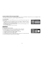
Page 39: ...or picture quality Note The System Menu will time out after 5 seconds if no buttons are pressed SYSTEM MENU SETTINGS AND ADJUSTMENTS The System Menu contains features and options that let the user customize the system For example the user can change the Picture FM Modulator OSD language source default screen mode display and the monitor mode Using the System Menu 1 Press the SYSTEM MENU button on ...

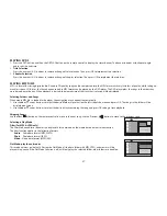
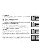
Page 40: ...s 2 Use the X cursor button to highlight wireless FM modulator WFMM 3 Use the T cursor button to highlight the FREQUENCY Submenu 4 Use the S T W or X cursor buttons to select a frequency not used by a radio station in the area Press OK to select the highlighted frequency There are a total of 5 FM CHANNEL pages containing frequencies from 88 1 MHz to 107 9 MHz in 0 2 MHz steps To access the additio...

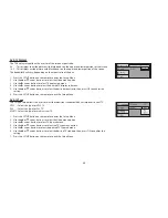
Page 41: ...mode of operation Selection of Source default can only be made from within the system menu SCREEN MODE This allows the user to change the screen format aspect ratio 16 9 4 3 To select the screen aspect ratio format 1 Press the System Menu button 2 Use the X cursor button to highlight SETTING 3 Use the T cursor button to highlight SCREEN MODE 4 Use the W or X cursor buttons to select 16 9 4 3 5 Pre...

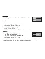
Page 42: ...mote control to exit the System Menu Mode IR TRANSMITTER This allows the user to turn the IR Transmitter ON or OFF The IR Transmitter must be set to ON for the wireless headphones to be operational 1 Press the System Menu button 2 Use the X cursor button to highlight SETTING 3 Use the T cursor button to highlight IR TRANSMITTER 4 Use the W or X cursor buttons to select ON or OFF 5 Press OK to conf...

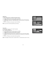
Page 43: ...he desired language 5 Press OK to confirm the setting FACTORY SETTING This allows the user to return the system to the factory default settings 1 Press the System Menu button 2 Use the X cursor button to highlight SETTING 3 Use the T cursor button to highlight FACTORY SETTING 4 Press OK to confirm the setting PICTURE WFMM SETTING DEFAULT DVD SCREEN MODE MONITOR MODE IR TRANSMITTER LANGUAGE FACTORY...

Page 44: ... back on the icon side of the setup page to set the other options Repeat steps 1 2 3 Press the SETUP button again to exit the Setup Menu LANGUAGE SETUP DVD Language for On Screen Display The Language Menu allows the user to select the language for the on screen display The user can select English French Spanish German or Italian for the OSD language 1 Press the SETUP button on the remote to enter ...

Page 45: ...ned in the disc DVD AUDIO SETUP The Audio Menu allows the user to select the language for audio 1 Press the SETUP button on the remote to enter the Setup Menu 2 Use the S or T cursor buttons to select the Language menu option 3 Use the X cursor button to select audio submenu 4 Use the T cursor button to select the audio option 5 Use the X cursor button to select audio submenu 6 Use the S or T curs...

Page 46: ...ct ratio then press OK to confirm the setting 6 Press the SETUP button on the remote to exit the Setup Menu DVD TV Type The TV Type setup allows the user to select the television standard which corresponds to your TV NTSC Select this type for NTSC TV PAL Select this type for PAL TV MULTI Select this type for multi system TV 1 Press the SETUP button on the remote to enter the Setup Menu 2 Use the S...

Page 47: ... to a unique password 1 Press the SETUP button on the remote to enter the Setup Menu 2 Use the S or T cursor buttons to select the Rating menu option 3 Use the X cursor button to select parental submenu 4 Use the S or T cursor buttons to select the change password menu option 5 Press OK to enter default password 3308 then press OK 6 Press OK again and key in a new 4 digit password then press OK to...

Page 48: ...ode ON Screen saver will appear OFF Screen saver will not appear 1 Press the SETUP button on the remote to enter the Setup Menu 2 Use the S or T cursor buttons to select the Misc menu option 3 Use the X cursor button to select the screen saver submenu 4 Use the T cursor button to select the screen saver option then press OK to enter the submenu 5 Use the S or T cursor buttons to select the screen ...

Page 49: ...pears automatically 1 Use the S or T cursor buttons to select the desired folder if present on the left side of the menu and press OK The songs in the folder will be displayed on screen 2 Use the S or T cursor buttons to select the desired track containing the song and press OK to begin track playback Skipping Songs Use the Next button on the remote control to move to the next song Use the Previou...

Page 50: ...rogram To add the selected songs into Browser view make sure disc playback is off Move the cursor to the Edit mode function and press OK After Edit mode is selected move cursor to songs list and select the songs which will be compiled Press OK A check mark appears to the left of the selected song To add the selected songs to the program move cursor to the Add to program function and press OK The s...

Page 51: ...n where the DVD player is sold A DVD from a different region cannot be played in this unit and the unit will display WRONG REGION Region 1 USA Canada Region 2 Japan Europe South Africa Middle East Greenland Region 3 S Korea Taiwan Hong Kong Parts of South East Asia Region 4 Australia New Zealand Latin America including Mexico Region 5 Eastern Europe Russia India Africa Region 6 China ...

Page 52: ...er Audio CD SACD DVD Audio Blu ray Discs Digital Copy Discs To load and play a disc Insert a disc into the disc slot The unit will turn on and start playing disc The disc slot indicator is red when a disc is inserted and green when the disc slot is empty Note If the unit is set to another source e g HDMI AV AUX Game etc inserting a disc in the disc slot will switch the unit to DVD mode and the DVD...

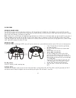
Page 53: ...me module containing 54 games 6 of which are two player games One Player Games Use the P1 controller to select and play games Two Player Games When there are two players the first player uses the P1 controller Player 2 uses the P2 controller The P1 controller is used for game selection The P2 controller can select a game but the game can only be started by pressing the START button on P1 controlle...

Page 54: ...layer to dry out No sound or distorted sound Make sure the DVD is connected properly Make sure all cables are securely inserted into the appropriate jacks If the 2 channel IR headphones are being used turn on the IR headphone power and make sure the correct channel A B is selected Make sure the FM Modulator is ON and the proper Frequency has been selected Make sure that unit is set to M1 when usin...

Page 55: ...t skipping through it HDMI MHL input not working for the HDMI MHL enabled device May require a special HDMI MHL adapter Contact your HDMI MHL device supplier for the adapter Game source does not work The Game source can not be selected grayed out if the MVGP1 Game Module is not installed Make sure the MVGP1 Game Module is installed and plugged in DTV source does not work The DTV source can not be ...

Page 56: ...PAL Video Output 1 0 Vp p 75 ohms Power Source 12 VDC Dimensions L x W x H 10 67 x 12 0 x 2 12 Closed 271mm x 305mm x 54mm Closed 10 67 x 12 0 x 8 97 Open 271mm x 305mm x 228mm Open Specifications are subject to change without notice REPLACEMENT PARTS SPECIFICATIONS Remote Control 136 5326 Wireless Headphones 136 5301 MVGP1 Game Module 136 5319 Game Controller P1 136 5320 Game Controller P2 136 53...

Page 57: ... by removal or defacement of the factory serial number bar code label s THE EXTENT OF THE COMPANY S LIABILITY UNDER THIS WARRANTY IS LIMITED TO THE REPAIR OR REPLACEMENT PROVIDED ABOVE AND IN NO EVENT SHALL THE COMPANY S LIABILITY EXCEED THE PURCHASE PRICE PAID BY PURCHASER FOR THE PRODUCT This Warranty is in lieu of all other express warranties or liabilities ANY IMPLIED WARRANTIES INCLUDING ANY ...

Page 58: ...www audiovoxproducts com 2013 Audiovox Electronics Corp 150 Marcus Blvd Hauppauge NY 11788 128 9229 ...

Page 59: ... our customer service staff stands ready to help Contact us at www audiovox com vPURCHASE REGISTRATION Registering on line will allow us to contact you in the unlikely event asafety notification is required under the Federal Consumer Safety Act L AUDIO O ELECTRONICS CORP Register Online at WWW AUDIOVOX COM Click on Product Registration and Fill Out the Brief Questionnaire ...

Reviews: