


64
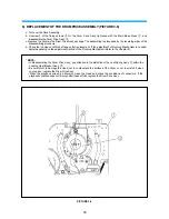
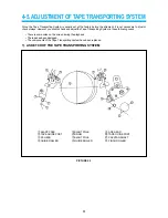
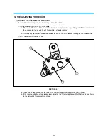
1-3) Height Adjustment for the Ace Head
a. Check if the gap between the lower part of tape and the lower part of CLT Head is 0.25mm.
b. If the gap is more than 0.25mm, turn the screw to the counter-clockwise direction as
!
→
@
→
#
step.
C. If the gap is less than 0.25mm, turn the screw to the clockwise direction as
!
→
@
→
#
step.
TAPE GUIDE POST
TAPE
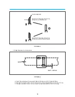
Adjust the TILT Adjustment Screw
@
by
turning to the clockwise direction
Adjust the TILT Adjustment Screw
@
by
turning to the counter-clockwise direction
PICTURE 5-3
GAP = 0.25mm
TAPE
PICTURE 5-4
Summary of Contents for AVP-7180
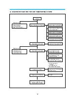
Page 16: ...3 2 CIRCUIT DIAGRAMS 15 1 CONNECTION DIAGRAM...
Page 17: ...16 2 POWER CIRCUIT DIAGRAM...
Page 19: ...18 3 SERVO SYSCON CIRCUIT DIAGRAM...
Page 21: ...20 4 VIDEO NOR AUDIO CIRCUIT DIAGRAM...
Page 23: ...22 5 Hi Fi PRE AMP CIRCUIT DIAGRAM...
Page 24: ...23 6 A V IN OUT CIRCUIT DIAGRAM...
Page 42: ...41 3 TIMING CHART OF S1 MECHA MECHANISM...
Page 46: ...45 B Deck bottom view...
Page 50: ...SKETCH OF JIGS AND TOOLS 49...
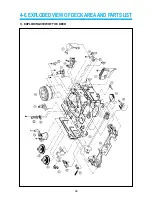
Page 70: ...4 6 EXPLODED VIEW OF DECK AREA AND PARTS LIST 69 1 EXPLODING VIEW OF THE DECK...
Page 71: ...70...
Page 74: ...AUDIOVOX SPECIALTY MARKETS CO LP 23319 COOPER DR ELKHART IN 46514 219 266 1886...


