


53
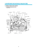
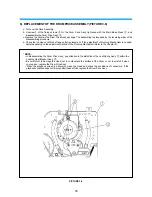
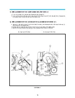
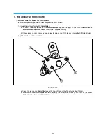
4). REPLACEMENT OF THE PINCH LEVER TOTAL ASSEMBLY (PICTURE 3-4)
a. Push the hook area of the Cassette Cap Opener
!
to the Y-axle direction and lift it up to separate from the Main
Base Press
@
. Be cautious of breakage of Hook.
b. Disassemble the Pinch Lever Spring
#
.
c. Disassemble the Pinch Lever Total Ass’y
%
next the Poly Washer
$
, but be careful not to contaminate the Pinch
Roller
^
.
d. Replace with new parts and assemble them by the reversing procedure of the disassembly.
PICTURE 3-4
Summary of Contents for AVP-7180
Page 16: ...3 2 CIRCUIT DIAGRAMS 15 1 CONNECTION DIAGRAM...
Page 17: ...16 2 POWER CIRCUIT DIAGRAM...
Page 19: ...18 3 SERVO SYSCON CIRCUIT DIAGRAM...
Page 21: ...20 4 VIDEO NOR AUDIO CIRCUIT DIAGRAM...
Page 23: ...22 5 Hi Fi PRE AMP CIRCUIT DIAGRAM...
Page 24: ...23 6 A V IN OUT CIRCUIT DIAGRAM...
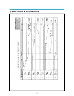
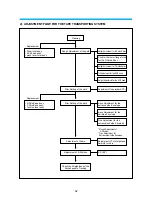
Page 42: ...41 3 TIMING CHART OF S1 MECHA MECHANISM...
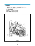
Page 46: ...45 B Deck bottom view...
Page 50: ...SKETCH OF JIGS AND TOOLS 49...
Page 70: ...4 6 EXPLODED VIEW OF DECK AREA AND PARTS LIST 69 1 EXPLODING VIEW OF THE DECK...
Page 71: ...70...
Page 74: ...AUDIOVOX SPECIALTY MARKETS CO LP 23319 COOPER DR ELKHART IN 46514 219 266 1886...