


36
2). DESCRIPTION OF THE MODES
!
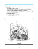
EJECT MODE
A. By rotating the L/C motor that runs the front loading to clockwise and counter-clockwise direction, the EJECT
mode conducts the cassette-in/out operations.
• Cassette-in operation: When a cassette is inserted with an adequate pressure, F/L Drive Rack falls out.
And the cassette-in driving starts on the point of time when the light is transmitted at the Start Sensor.
If there is no safety tab in a cassette, the Deck mode transfers to the Playback mode.
• The cassette-out operation: The Cassette Holder Assembly is located at the entrance of the Front Panel, and
it only conducts the cassette in operation, when the Cassette Holder Assembly will be locked by the safety
lever-R/L in order to protect the cassette tapes.
B. The configuration of appliances
a. The Band Brake is separated from the S-Reel Table.
b. The S/T Sub Brake is attached to the S/T-Reel Table.
c. The Idler Gear is attached to the S-REEL Table.
EJECT MODE
Summary of Contents for AVP-7180
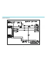
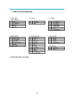
Page 16: ...3 2 CIRCUIT DIAGRAMS 15 1 CONNECTION DIAGRAM...
Page 17: ...16 2 POWER CIRCUIT DIAGRAM...
Page 19: ...18 3 SERVO SYSCON CIRCUIT DIAGRAM...
Page 21: ...20 4 VIDEO NOR AUDIO CIRCUIT DIAGRAM...
Page 23: ...22 5 Hi Fi PRE AMP CIRCUIT DIAGRAM...
Page 24: ...23 6 A V IN OUT CIRCUIT DIAGRAM...
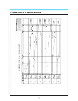
Page 42: ...41 3 TIMING CHART OF S1 MECHA MECHANISM...
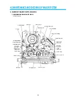
Page 46: ...45 B Deck bottom view...
Page 50: ...SKETCH OF JIGS AND TOOLS 49...
Page 70: ...4 6 EXPLODED VIEW OF DECK AREA AND PARTS LIST 69 1 EXPLODING VIEW OF THE DECK...
Page 71: ...70...
Page 74: ...AUDIOVOX SPECIALTY MARKETS CO LP 23319 COOPER DR ELKHART IN 46514 219 266 1886...