ATS Axsis SC-300H Operation And Reference Manual Download Page 29


Operations and Reference Manual 


Axsis™ SC-300H Digital Radar Speed Camera 


2011 American Traffic Solutions, Inc. 


Page 27


 Proprietary and Confidential 

All Materials are subject to change without notice.

 6/30/2011


10. 

D

IGITAL 

C

AMERA 

S

ETUP


The followin g is a  very basic explanation of t he camera  setup.  For  more detailed camera  

information, please  ref erence “Th e Nikon Gu ide to Dig ital Photogra phy with th e D2x Digital  

Camera”. 

10.1


C

AMERA 

ON


/


OFF

 AND 

S

HUTTER 

R

ELEASE


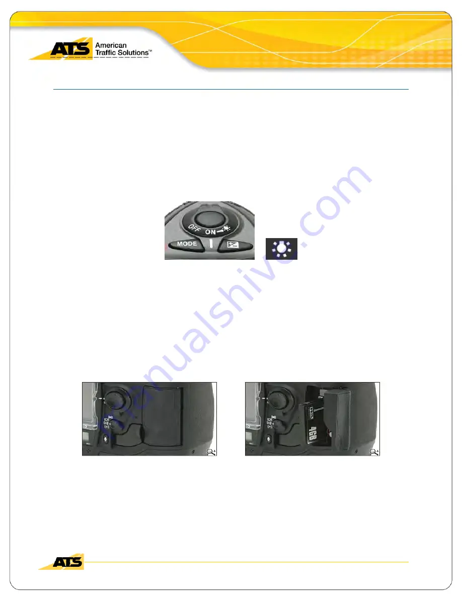
Rotate the power switch to the desired ON or OFF setting. 
Further switch rotation past ON, to the light  bulb setting, will illuminate the top and rear  

control panels. 
The round button in the center of the power switch is the shutter- release button.


Camera ON/ OFF and Shutter Release 

10.2


M

EMORY 

C

ARD 

I

NSERTION 

/


R

EMOVAL


The camera power should be OFF before inserting or removing the memory card. 
The Compact Flash (CF) memory card slot is located behind a protective door. 
To open the CF protective door, pivot the latch, press the release button and open the door.   
When inserting a memory card make sure  it is  oriented correctly before insertion  or you could 

damage the card. 
To eject a memory card, press the gray eject button located above the memory card. 


Memory Card Insertion / Removal 


Summary of Contents for Axsis SC-300H

Page 1: ...ent American Traffic Solutions 360 Herndon Parkway Model SC 300H Suite 1400 FCC ID KXRSC 300H Herndon VA 20170 Standards FCC Part 90 http www rheintech com Report 2011088 22 of 26 Appendix J Manual Please refer to the following pages ...

Page 2: ... 300H Digital Radar Speed Camera Single Camera System June 2011 American Traffic Solutions 7681 East Gray Road Scottsdale Arizona 85260 480 44 3 7000 480 60 7 0901 www atsol com www redlightcamera com Proprietary and Confidential Information ...

Page 3: ...ING BATTERY BOX 15 3 1 EXPLANATION 15 3 2 PURPOSE OF THE SWITCH SETTINGS 15 3 2 1 Charging Side 15 3 2 2 Static Auxiliary Side 15 3 3 PROPER SWITCH SETTINGS 16 3 3 1 Morning Shift 16 3 3 2 Afternoon Shift 16 3 3 3 While vehicle is not in use and plugged in 16 4 COMPONENT INTERCONNECTIONS 17 4 1 SINGLE CAMERA WIRING SCHEMATIC 17 5 TECHNICAL REFERENCE MATERIAL 18 5 1 AIMING THE RADAR UNIT 18 5 2 SID...

Page 4: ...F RADIATION EXPOSURE STATEMENT 21 7 CAMERA FIELD OF VIEW AND RADAR BEAM PATTERN DIAGRAM 22 7 1 RECEDING MODE FOV AND RADAR BEAM PATTERN 22 8 PRE DEPLOYMENT CHECK 23 8 1 360 WALK AROUND 23 9 DIGITAL CAMERA NIKON MODEL D2X 24 10 DIGITAL CAMERA SETUP 27 10 1 CAMERA ON OFF AND SHUTTER RELEASE 27 10 2 MEMORY CARD INSERTION REMOVAL 27 10 3 MEMORY CARD FORMATTING 28 10 4 LENS INSERTION 29 10 5 LENS REMOV...

Page 5: ...SH SYNC TIMING AT NIGHT 41 14 FOCUSING THE LENS 42 14 1 SETTING THE FOCUS MODE 42 14 2 USING MANUAL FOCUS 42 14 3 USING AUTO FOCUS 43 14 4 SELECTING THE APPROPRIATE FOCUS SQUARE 44 14 5 WHERE YOU SHOULD BE FOCUSING 44 14 6 TAKING YOUR TEST SHOT 45 14 7 ALWAYS FOCUS ON THE FURTHEST LANE AWAY FROM YOU 46 14 8 REVIEWING TEST SHOTS 47 14 9 BETTER FOCUS USING VERTICAL AXSIS ADJUSTMENT 48 15 SYSTEM OPER...

Page 6: ...thout notice 6 30 2011 15 14 END DEPLOYMENT 64 15 15 CD BURN PROCESS END OF DAY OR AFTER THE LAST DEPLOYMENT 66 15 16 HELP ABOUT 66 16 LABELING THE CD DVD 67 17 SC 300H UPLOAD PROCESS END OF DAY OR AFTER THE LAST DEPLOYMENT 68 17 1 OVERVIEW 68 17 2 SCREENSHOT WALKTHROUGH 68 17 2 1 The Upload button 70 17 2 2 The Skip Upload button 73 18 SAMPLE TRACKING SHEET 75 19 ADDITIONAL NOTES 76 ...

Page 7: ...allel to the Flow of Traffic 23 Nikon model D2x 24 Nikon model D2x Functions Front and Side 24 Nikon model D2x Functions Top 25 Nikon model D2x Metering selector 25 Nikon model D2x Functions Back 26 Camera ON OFF and Shutter Release 27 Memory Card Insertion Removal 27 Format Memory Card 28 Nikon Lens Insertion 29 Lens Aperture Setting 29 Lens Release Button 30 A M and VR ON OFF Buttons 30 Shooting...

Page 8: ...ea Mode Selector 43 Auto Focusing the Lens 43 Focus Areas Multi Selector and Focus Selector Lock 44 Vehicle in Furthest Lane Away Focused for Plate 45 Vehicle in Furthest Lane Away Focused for Plate 46 Vehicle in Near Lane When Furthest Lane Was Focused 46 Reviewing Test Shots Work Flow 47 Vertical Adjustment Tripod Handle and Tripod Mount Knobs 48 Positioning Your Focus Square for Optimum Auto Fo...

Page 9: ...elf Test Passed 61 Test Shot 62 Continue Arming 63 Continue Radar Armed 63 End Deployment Button 64 Self Test in Progress 64 Self Test Success 65 Transfer Button 65 Deployment Ended 65 CD Burn Process 66 Help About 66 Labeling Guide for the CD DVD 67 Labeling Guide for the CD DVD Envelope 67 Programs SC 300H Upload Files Residence 68 Connection Error Dialog 69 SC 300H Upload GUI Connected and No W...

Page 10: ...c Solutions Inc Page viii Proprietary and Confidential All Materials are subject to change without notice 6 30 2011 Cancelation Status Dialog 73 Unable to Cancel Uploads Dialogue Screen 73 Confirmation Screen Skip Uploading 73 GUI State Uploaded Archived and Skipped 74 Sample Tracking Sheet 75 ...

Page 11: ...following sections 1 Introduction 2 Capture System Components 3 Operating the Self Charging Battery Box 4 Component Interconnections 5 Technical Reference Material 6 Occupational Exposure of Personnel 7 Camera Fields of View and Radar Beam Pattern Diagrams 8 Pre Deployment Check 9 Digital Camera Nikon model D2x 10 Digital Camera Setup 11 Camera Matrix Settings 12 Changing Camera Settings 13 Camera...

Page 12: ...istics for display on the o perator s Laptop PC The syste m digitally photographs vehicles traveling over a designated trigger speed limit and saves the following The speed data from the Radar Unit Date time and location data Rear image of receding vehicles in up to four lanes taken when the Radar Unit detects an offending vehicle The system produces images that allow the review operat or to uniqu...

Page 13: ...f connection and physical setup the radar ant enna radar controller a nd the dig ital camera USB interface circuit bo ards are all housed in a single protective enclosure that mounts in the deployment vehicle on a post Tilt and Swivel Head configuration Axsis SC 300H Speed Camera System 2 2 RADAR BASE MOUNT ASSEMBLY The mounting system f or the Radar Base Unit consist s of two parts a mounting bas...

Page 14: ...e subject to change without notice 6 30 2011 2 3 DIGITAL CAMERA MOUNTED AND RADAR BASE UNIT This camera will be taking single sho ts of the rear of vehicles as they are driving away from the deployment vehicle to capture their license plate 2 4 SYSTEM LAPTOP ON SPECIAL MOUNT System Laptop on Special Mount Camera and Radar Unit From Inside the Deployment Vehicle ...

Page 15: ...oprietary and Confidential All Materials are subject to change without notice 6 30 2011 2 5 STROBE AND HEAVY DUTY POWER INVERTER The system strobe light is powered via a dedicated heavy duty power inverter and uses a handy magnetic mount mechanism Strobe and Heavy Duty Power Inverter 2 6 STROBE LOCATION Strobe placement ...

Page 16: ... is set to the appropriate position th e furthest to the right clockwise that the knob will go Power Pak 2 8 BATTERY BOX AND CHARGER The SC 300H system uses a Battery Box to house two 12 V DC batteries and is mounted in the rear of the deployment vehicle DC system p ower and AC strobe power is then distributed where required to the individual components via a power distribution box located on the ...

Page 17: ...ing Side These are the two switches on the left side of th e battery box Whichever settings the switches are turned to is which batteries will be charging 1 When the two switches are on set to 1 you will be charging the LEFT battery 2 When those switches are set to 2 you will be charging the RIGHT battery 3 When those switches are set to 1 2 you will be charging both batteries 4 When those switche...

Page 18: ...g fork test set the charging switches left switches to position 1 And set the Auxiliary Switches to position 2 3 3 2 Afternoon Shift Before starting the tuning fork test set the charging switches left switches to position 2 And set the Auxiliary Switches to position 1 3 3 3 While vehicle is not in use and plugged in Make sure the following equipment is off 1 Radar 2 Camera 3 Strobe Generator 4 Lap...

Page 19: ...Radar Speed Camera 2011 American Traffic Solutions Inc Page 17 Proprietary and Confidential All Materials are subject to change without notice 6 30 2011 4 COMPONENT INTERCONNECTIONS 4 1 SINGLE CAMERA WIRING SCHEMATIC SC 300H Single Camera Wiring Schematic ...

Page 20: ... correctly across the road 2 Insure that the vehicles are visible in the photo graph regardless of t he lane in which vehicles are traveling 5 4 ESTABLISHING CORRECT RADAR BEAM ANGLE The radar beam must b e angled across the roa d at 22 5 degrees from parallel Th e correct Z Axsis orientation is normally set by a trained Radar technician 5 5 TUNING RADAR CONTROLLER TO THE RADAR ANTENNA To insure a...

Page 21: ...6 12 Operating Road Speeds Minimum 15mph 24 1 km h Maximum 185mph 297 7 km h 5 6 13 Temperature Highest 140 ºF 60 ºC Lowest 10 ºF 23 3 ºC 5 6 14 Roadway Displacement Distance 12ft nominal 2 ft to center of nearest lane of traffic being measured 3 6576 m nominal 0 6096 m to center of nearest lane of traffic being measured 5 6 15 Temperature and Humidity 120 ºF non condensing 48 9º C non condensing ...

Page 22: ... marin e etc the power levels of poli ce traffic radar devices are orders of magnitude lower The emitted power of traffic radar de vices is lo wer than or comparable to other microwave or radiofrequen cy RF radiation emitting devices used in close proximity to persons in the general public such as garage door openers cellu lar telephones and infant monitors Speed control radars are used by police ...

Page 23: ...of damage occurs to tissues from repeated low level RF exposure At present there is no substantive evidence that adverse health effects including cancer can occur in people exposed to RF levels at or below the limits set by international standards Always point the device away from the operator s body or any other persons while it is turned on Mount fixed radar antennas so that the beam is not poin...

Page 24: ... user s authority to operate this equipment 7 CAMERA FIELD OF VIEW AND RADAR BEAM PATTERN DIAGRAM 7 1 RECEDING MODE FOV AND RADAR BEAM PATTERN Receding Mode Deployment Violation Point 22 5 degree radar beam angle offset from 0 degrees 4 7 degree horizontal beam width 14 degree vertical beam width Camera FOV overlays radar beam to put plate in center of camera lens FOV Receding mode violation point...

Page 25: ...t parking parallel to the flow of traffic will throw off the radar readings Check your environment Are there any tree branches bushes or other objects blocking the camera FOV or the strobe Inspect strobe positioning Make sure the stro be is pointe d in the sa me direction as your camera lens Make sure your windows are extremely clean This will make focusing much ea sier and your images clearer Mak...

Page 26: ...ican Traffic Solutions Inc Page 24 Proprietary and Confidential All Materials are subject to change without notice 6 30 2011 9 DIGITAL CAMERA NIKON MODEL D2X The digital camera used in the SC 300H System is the Nikon model D2x Nikon model D2x Nikon model D2x Functions Front and Side ...

Page 27: ...sis SC 300H Digital Radar Speed Camera 2011 American Traffic Solutions Inc Page 25 Proprietary and Confidential All Materials are subject to change without notice 6 30 2011 Nikon model D2x Metering selector Nikon model D2x Functions Top ...

Page 28: ...erence Manual Axsis SC 300H Digital Radar Speed Camera 2011 American Traffic Solutions Inc Page 26 Proprietary and Confidential All Materials are subject to change without notice 6 30 2011 Nikon model D2x Functions Back ...

Page 29: ...g Further switch rotation past ON to the light bulb setting will illuminate the top and rear control panels The round button in the center of the power switch is the shutter release button Camera ON OFF and Shutter Release 10 2 MEMORY CARD INSERTION REMOVAL The camera power should be OFF before inserting or removing the memory card The Compact Flash CF memory card slot is located behind a protecti...

Page 30: ... A blinking For will appear in the top control panel and the frame count will blink Now simult aneously press both bu ttons a second time to start the formatting process The Memory Card Access Lamp by the memory card door lat ch will illuminate Once formatting is complete the green active indicator light will turn off and the frame count display will show the number of photos that can be recorded ...

Page 31: ...nting mark on the lens with the mounting mark on the camera body Position the lens into the camera s bayonet mount Being careful not to press the lens release button rotate the lens counter clockwise until it clicks into place Nikon Lens Insertion NOTE When installed make certain the lens aperture setting is at the minimum setting highest F stop number If the initial lens F Stop setup is ignored a...

Page 32: ...de selector Rotate the lens clockwise until it unlatches from the camera s bayonet mount Lens Release Button 10 6 LENS SETTINGS Some lenses have additional settings for focus mode and vibration reduction right on the lens If your lens features these settings they should be set as follows A M button should always be set to A so that the camera can control the auto focus If for some reason you must ...

Page 33: ...dential All Materials are subject to change without notice 6 30 2011 10 7 SHOOTING MODE Press the Mode Dial Lock Release button located on the top left of the camera and rotate the mode dial to the S Single Frame position This will allow you to take one picture each time you press the shutter release button all the way down Shooting Mode ...

Page 34: ...aytime Poor Weather Indirect sun on Plates Night Strobe light on Plates Exposure Mode Manual Manual Manual Manual Shutter Speed 1250 1000 1000 800 Aperture F 7 1 F 6 3 F 6 3 F 5 6 Focus Area Single Area Center Single Area Center Single Area Center Single Area Center Sensitivity 640 640 640 640 White Balance Flash Flash Flash Flash Data Format Jpeg 8 bit Jpeg 8 bit Jpeg 8 bit Jpeg 8 bit Jpeg Qualit...

Page 35: ...oftware once the camera is plugged into the USB port Changing camera settings on the camera commonly requires you to use the main command dial or the sub command dial pictured below Main Command Dial Sub Command Dial 12 1 EXPOSURE MODE To change the exposure mode press the Exposure Mode Button and rota te the Main Command Dial The Selected Mode will display in the top control panel There are four ...

Page 36: ... Sp eed the larger number in the mid dle of the display can be selected by rotating the Main Command Dial 12 2 2 Changing Aperture The Aperture F on the right is selected by rotating the Sub Command Dial Shutter Speed and Aperture on Top Control Panel 12 2 3 Changing Exposure Mode Shutter Speed and Aperture in Nikon Capture Camera Control In Nikon Capture Camera Control the exposure mode shut ter ...

Page 37: ... the monitor If you are unable to move t he focus area rotate the focus selector lock located outside the multi selector Focus Areas Multi Selector and Focus Selector Lock You will typically want to use the middle or bottom middle focus area 12 4 SENSITIVITY EQUIVALENT TO ISO FILM SPEED To set or c hange the sensitivity press the sensitivity ISO button and rotate the Main Command Dial to the appli...

Page 38: ...and White Balance WB in Nikon Capture Camera Control In Nikon Capture Came ra Control the Focus A rea Sensitivity ISO a nd White Balance WB settings can also be changed under the Exposure 2 tab Focus Area Sensitivity and White Balance 12 6 JPEG QUALITY The Jpeg quality settin gs are Fine Normal or Basic To set or change press the Imag e quality size QUAL button and rotate the Main Command Dial nor...

Page 39: ... SIZE The Image Size settin gs are Large Medium or Small T o set or change press the Image quality size QUAL button and rotate the Sub Command Dial normally set to Large Image quality size QUAL button 12 7 1 Changing Jpeg Quality and Image Size in Nikon Capture Camera Control In Nikon Capture Camera Control the Jpeg Quality and Image Size settings can also be changed under the Storage tab Jpeg Qua...

Page 40: ...hs which allows you to precisely control the field of view FOV The FOV is d etermined by the focal length of the lens The focal length is measured in millimeters 55mm FOV License Plate Camera 13 2 ADJUSTING FIELD OF VIEW ZOOMING The FOV can be set by twisting the large rubber ring on the lens back and forth while looking through the viewfinder This zooms your lens in and out The focal length is de...

Page 41: ...mount arms and or the tripod mount knobs to adjust the camera or radar unit Th is will a llow you to tilt upwards or downwards vertically Vertical Adjustment Tripod Handle and Tripod Mount Knobs 13 4 HORIZONTAL AXSIS ADJUSTMENT You may also need to use the tripod mount arms and or t he tripod mount knobs to adjust the camera or radar unit This will giv e you a straight horizo n line no matter how ...

Page 42: ...ithout notice 6 30 2011 13 5 SELECT FIELD OF VIEW FOR RECEDING ONLY TRAFFIC PLATE CAMERA Select the FOV that is most appropriate for th e number of lanes in yo ur deployment The idea here is to zoom in as much as possible for better plate identification without losing details of the vehicle s make and model and some of the environment in the background Vehicle Lane 1 Vehicle Lane 2 ...

Page 43: ... notice 6 30 2011 13 6 FLASH SYNC TIMING AT NIGHT It is very important that the vehicles plates are fairly close to the center of the field of vie w vertically or lower At night when using a strobe the camera shutter will cause the top 1 3 of the frame to darken If the rear plate is in this top 1 3 it will be very difficult or impossible to get a clear plate shot Correct FOV Incorrect FOV ...

Page 44: ...Mode The camera will continuously refocus the lens on moving objects as long as the shutter release is pressed halfway down S Single Servo Auto Focus The camera will auto focu s once when the shutter release is pressed halfway down M Manual Mode The camera will not auto focus when the shutter release is pressed halfway down The lens must be manually focused by turning the rubber ring on the lens 1...

Page 45: ...NG AUTO FOCUS First make sure that the focus mode selector switch on the front of the camera is set to C or S to turn on the camera s auto focus Focus Mode Selector Next set the AF area mode selector to the bottom square AF Area Mode Selector Now to use the camera s auto focu s press half way down on the shutter release button or press the AF ON button on the back right corner of the camera Auto F...

Page 46: ... back of the camera to the right of the monitor If you are una ble to move the focus area rotate the focus selector lock located outside the multi selector You can also change this setting in Nikon Capture Camera Control under the Exposure 2 tab 14 5 WHERE YOU SHOULD BE FOCUSING The lane that you should be focusing on will always be the furthest lane away from you that you are monitoring on that d...

Page 47: ...h the viewfinder and w ait for a vehicle in the appropriate lane to en ter the FOV When you see the vehicle you wish to focus on press th e shutter r elease butt on half way down to auto focus and all the way down to take a picture You should be pressing the button only when the plate is directly in the focus square you selected This takes some practice to get the exact timing down so be patient V...

Page 48: ...e far lane we still get very good focus on the near lane because the plate is nearly twice the size So even though the focus is not as sharp on the near lane we still get a very readable plate Vehicle in Furthest Lane Away Focused for Plate If we had focused on the near lane it would have been nearly impossible to read th e plate in the far lane because it would be out of focus and half the size o...

Page 49: ...ackground The driver s faces or plate should be the sharpest thing in the photo Anything in the background should be softer focus If the plate is not the sharpest thin g in the ph oto take an other test shot and review on the laptop Repeat this until the photo is in proper focus Once you are satisfied with your focus set the Focus Mode Selector switch to M This locks in the current camera focus Af...

Page 50: ...uares direct ly over the plate the vertical axsis adjustment can help you Vertical Adjustment Tripod Handle and Tripod Mount Knobs You can use this adju stment to move the FOV up or down to better position your f ocus square for precise focusing Positioning Your Focus Square for Optimum Auto Focus Performance Once you are satisfied with your focus set the Focus Mode Selector switch to M This locks...

Page 51: ...rly connected and then turn on the Axsis SC 300H Radar Base Unit Make sure a Data Card i s inserted into each camera s data card slot refer to section 8 2 Turn on both Digital Cameras Double click the SC 300 Icon on t he laptop d esktop Th e following SC 300H initial startup screen should display Initial Startup Screen 15 1 INITIAL STARTUP SCREEN OPERATOR SELECTION Select the Operator fi eld down ...

Page 52: ... operator selection the system will immediately open a second window and re quest entry of a Badge Number Initial Startup Screen Badge Number The correct badge number must be entered to proceed to t he deployment number selection If a number is entered that the system does not recognize as valid you will see the box below Initial Startup Screen Invalid Badge Number Click the OK button and try your...

Page 53: ...al All Materials are subject to change without notice 6 30 2011 15 2 DEPLOYMENT NUMBER Complete the Deployment Number by filling in the Depl No field This will be a three dig it number that is assigned to a deployment location Deployment Number Screen Enter the appropriate deployment number into the Depl No field Deployment Number Screen Entry ...

Page 54: ...SELECTION Select the Location f ield down arrow to open and display the current list o f previously approved system locations From this list select highlight the appropriate location The system will automatically fill in the Location Description Posted Speed and Trigger Speed for the selected location Initial Startup Screen Location Selection Note that adding or editing an operator and or location...

Page 55: ...0 2011 15 4 DIRECTION Select the Direction field down arrow to ope n and display the current list of direction options Select the option that is appropriate to your deployment Direction Once all of the Location Details have been entered click the Next button at the bottom A Confirm Settings screen will appear Confirm Settings Double check all displayed information and click the appropriate Yes or ...

Page 56: ...es necessary and then click th e time and date confirmation box Note that any changes made to the time and or date will also update the laptop to maintain synchronization Time and Date Entry and Confirmation Checking the box next to Time and date are co rrect will confirm the Current Time and Date by graying them out T he Next b utton w ill now be highlighted to enable advancing to th e operationa...

Page 57: ...ing operational screens will be presented Current Settings Violation Statistics Event History Pause Button End Deployment Button SC 300H Speed Camera System Operational Screen Note The operational screen also displays the current operational status in the bottom left corner The above example shows that the deployment is initializing At this point the system will reach out to the camera and take te...

Page 58: ...deploy ment when the r adar first start s recording vehicles o n this screen it is very important that you verify the information displayed is correct Make sure that the location poste d speed and trigger speed are accurate This information will show on the data bar of all violations recorded If it is inaccurate the violations are not useable 15 8 VIOLATION STATISTICS The Violation Statistics disp...

Page 59: ...6 30 2011 15 9 EVENT HISTORY The Event History shows the last vehicle speed an indication of whether or not t he vehicle was a violator and the Radar Voltage Also displaye d are the Output Tab a nd the Last Photo Event Tab 15 9 1 Output Tab The Output tab displays a Stack list of the newest to oldest vehicles speeds as they were passing the radar and what their status was Output Tab Event History ...

Page 60: ...re subject to change without notice 6 30 2011 During the deployment sequential events will be displayed in the stack to provide an ongoin g report of vehicle detection The events are color coded as follows violations displayed in red voids displayed in blue non violations displayed in black tests displayed in olive success displayed in green Stack Event Colors ...

Page 61: ...ed signal to be inconsistent Void Tab An excessive amount of voids could suggest t hat there is a problem with the ra dar or the deployment location 15 9 3 Last Photo Event Tab This is a new tab within the Axsis SC 300H Speed Camera System It allows the user to view the images immediately as they happen There is a small delay however the oper ator will be able to see the violation picture righ t f...

Page 62: ...30 2011 15 10 PAUSE BUTTON If an Opera tor wishes to temporarily suspend the deployment for conditions su ch as traffic congestion adverse weather etc or to temporarily distract attention away from the deployment activate the Pause button Radar Paused will then displa y at the bottom left hand corner of the screen Pause When full attention will be back on the deployment activate the Continue Butto...

Page 63: ... 2011 15 11 SELF TEST While the system is paused when you click the Self Test button it will send a command to the radar to engage a self test During the Self Test a Self Test in progress or Self Test Passed message will display in the lower left hand corner of the screen Self Test in Progress Once the self test is complete it will display as an event in your stack in the Output Tab Self Test Pass...

Page 64: ...All Materials are subject to change without notice 6 30 2011 15 12 TEST SHOT While the system is paused when the Test Shot button is clicked it triggers the camera to take a test picture It is not necessary for a vehicle to be in the radar beam for this to trigger Test Shot Once the Test Shot is complete it will display as an event in your stack ...

Page 65: ...tice 6 30 2011 15 13 CONTINUE While the system is paused when the Continue bu tton is clicked it triggers the system to arm the radar Notice that Arming will display in the lower left hand corner of the screen Continue Arming Once the arming of the radar is complete it will then display Radar Armed The Pause button now returns for use in the event you need to pause again Continue Radar Armed ...

Page 66: ...2011 15 14 END DEPLOYMENT When you are ready t o end your deploymen t clic k the End button This will display th e following screen and then initiate an End Deployment Test Shot sequence as well as an En d Deployment Calibration Test End Deployment Button At this point quickly write down your violation statistics for your paperwork They d o not stay posted on the screen very long Self Test in Prog...

Page 67: ...ithout notice 6 30 2011 Self Test Success Once the self test is complete the system will prompt to start the image download Transfer Button Click the Transfer Button to start do wnloading the images from your da ta card Insert the card as the system prompts Do not remove the last data card from the card reader until the following message appears on the laptop screen Deployment Ended ...

Page 68: ...notice 6 30 2011 15 15 CD BURN PROCESS END OF DAY OR AFTER THE LAST DEPLOYMENT Load a new blank DVD R CD in the DVD CD drive and press the Burn button CD Burn Process When the CD DVD burning is complete the CD DVD will automatically eject Label the CD DVD and return to be processed 15 16 HELP ABOUT The Help About menu allows the user to see what version they are currently using Help About ...

Page 69: ...re subject to change without notice 6 30 2011 16 LABELING THE CD DVD It is recommended that you fill out your CD DVD and envelope as follows Please make sure your deploymen t discs and sleeves follow the proper identificat ion forma t below and are done neatly Make sure your writing is legible Labeling Guide for the CD DVD Labeling Guide for the CD DVD Envelope ...

Page 70: ... software to make use of this feature When prompted the op erator may be able to select Upload instead of Burn to CD DVD If Upload is selected then the deployment files on the operator s laptop will be moved to a target location monitored by the SC 300H Upload service After SC 300H operations are completed and the operator is connected to the internet they can enter the SC 300H Upload GUI to uploa...

Page 71: ...onnect to the FTP server It will be one of Connected Not Connected or Connection Error If it isn t Connected co ntact you r supervisor Connection Error Dialog At the start of a shift the message No waiting jobs sh ould be displayed If there are any folders waiting upload note the na mes of the f older and fo llow standard operating procedures these may vary between notifying your supervisor to att...

Page 72: ...oprietary and Confidential All Materials are subject to change without notice 6 30 2011 After conducting deployments deployment folders should appear under Transfer Folder Status After Transfer and Marked for Upload 17 2 1 The Upload button Clicking on the Upload button will start the upload process Files Being Uploaded ...

Page 73: ...ials are subject to change without notice 6 30 2011 Once the files are successfully uploaded your dialogue box will look like the one below showing that the folder was uploaded and archived Files Successfully Uploaded and Archived If an error occurs whil e the information is archiving you will see the Error message und er Archived Error Failed to Archive ...

Page 74: ...y and Confidential All Materials are subject to change without notice 6 30 2011 If this error occurs click the Retry Failed Archives button to try again Archive Process Retried and Successful At anytime during the upload process the op erator can hit the Can cel Button and will b e prompted to confirm Confirmation Cancel Upload ...

Page 75: ... Status Dialog If you cancel an upload but it had already completed uploading you may see this dialog screen Unable to Cancel Uploads Dialogue Screen 17 2 2 The Skip Upload button If the operator has been instructed to skip upload by a supervisor the operator will be prompted to confirm and will be instructed what to do in this event Clicking on the skip upload button will skip the upload process ...

Page 76: ...mpleted uploads as well as failed skipped or oth er problems For exa mple the above folder 20090427 _064024 was uploaded successfully and the folder 20090413_055903 was skippe d and 2009 0407_054543 has not been processed 20090407_054543 could still be burned to DVD or it could be uploaded The SC 300H Upload does not always refresh so if ever t he text is garbled right click the ico n in the task ...

Page 77: ...anual Axsis SC 300H Digital Radar Speed Camera 2011 American Traffic Solutions Inc Page 75 Proprietary and Confidential All Materials are subject to change without notice 6 30 2011 18 SAMPLE TRACKING SHEET Sample Tracking Sheet ...

Page 78: ...nd Reference Manual Axsis SC 300H Digital Radar Speed Camera 2011 American Traffic Solutions Inc Page 76 Proprietary and Confidential All Materials are subject to change without notice 6 30 2011 19 ADDITIONAL NOTES ...

Reviews: