


- 101 -
FUEL SYSTEM
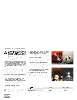
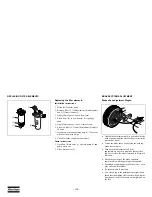
PRIMING INSTRUCTIONS
Prime the fuel system in order to fill the fuel filter.
Prime the fuel system in order to purge trapped air.
The fuel system should be primed under the following
conditions:
•
Compressor is put in operation for the first time
•
Running out of fuel
•
Storage
•
Replacement of the fuel filter
Key-on priming (if equipped)
1. Turn the engine start switch to the ON position.
Leave the engine start switch in the ON position
for 2 minutes.
2. Verify that the water separator is full of fuel.
3. If the water separator is not full of fuel, turn the
engine start switch OFF and then turn the engine
start switch ON. Turning the switch OFF, then ON
will cycle the fuel priming pump again.
4. When the water separator is full of fuel, attempt to
start the engine. If the engine starts and the engine
runs rough or the engine misfires, operate at low
idle until the engine is running smoothly. If the
engine cannot be started, or if the engine
continues to misfire or smoke, repeat Step 1.
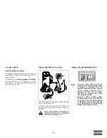
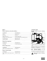
Manual switch priming (if equipped)
The manual switch is located on the primary filter
base/electric priming pump assembly.
1. Hold the manual switch in the up position until
fuel has filled the water separator.
2. Continue to hold the switch for 30 seconds after
the water separator is full.
3. Attempt to start the engine. If engine starts and
runs rough or misfires, operate at low idle until the
engine is running smoothly. If the engine cannot
be started, continue to prime the fuel system for 30
more seconds.
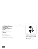
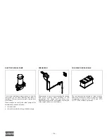
Fuel leaked or spilled onto hot surfaces
or electrical components can cause a fire.
To help prevent possible injury, turn the
“ON/OFF” switch in position “OFF”
when changing fuel filters or water
separator elements. Clean up fuel spills
immediately.
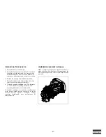
Do not loosen the fuel lines at the fuel
manifold. The fittings may be damaged
and/or a loss of priming pressure may
occur when the fuel lines are loosened.
Do not allow dirt to enter the fuel system.
Thoroughly clean the area around a fuel
system component that will be
disconnected. Fit a suitable cover over
disconnected fuel system component.
Summary of Contents for XRVS 1350
Page 2: ......
Page 24: ... 24 FLOW DIAGRAM EXHAUST AFTERTREATMENT HPFP DOC EAM DPF ...
Page 30: ... 30 SH4 COMPRESSOR CIRCUIT 9822 0963 68 ...
Page 135: ......
Page 136: ......


