- 105 -
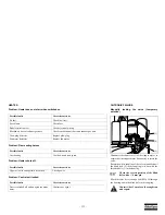
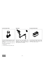
Cleaning instructions filter element
Open the coupling head by pushing the lid (5) into the
housing as far as it will go and turning it by 90° using
an Allen key.
Remove the spring (4), the metal ring (3) and filter (2)
from the housing.
Clean the housing (1) using a clean cloth.
Clean the filter (2) or replace it if really dirty or
damaged.
Check the seal (6). Replace if damaged.
Lubricate the seal (6) with some grease.
For assembly insert the metal ring (3) into the spring
(4) with its side facing down.
Place the filter (2) and filter body inside the spring (4)
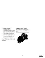
facing down (Picture: dismantled coupling head).
Transfer the spring (4) back into the housing.
Put the lid (5) on the housing's opening. Push the lid
down as far as it will go and lock it using the Allen
key and turning it by 90°.
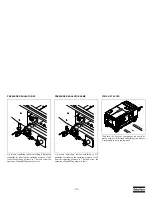
Draining the brake system
If the system is not regularly drained, water residues
may be left inside which in the worse case scenario
block the brakes.
To stop the brake system from freezing in winter we
recommend you use an anti-freeze agent.
You have to drain all the compressor's brake system
compressed air tanks.
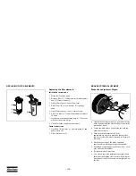
The drainage valves can be found in the middle
underneath the tanks.
Pull the activation bolt of the drainage valve to the
side. Hold the bolt until no more condensation water
is coming out. Release the activation bolt. The
drainage valve will close.
Defective or leaking valves have to be replaced.
Tyres
Tyre check
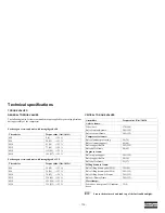
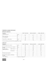
Check the tyre pressure and tread.
Refer to the table in chapter
Technical
specifications
.
Tyre change
When changing tyres please pay attention to the
following.
Take direction of wheel travel into consideration.
Check the tyre pressure.
Prior to fitting the wheel nuts you should oil the
threads (do not use oil with molybdenum disulphide
additives).
Make sure that the tyres have the same tread.
Secure the compressor against rolling by using the
wheel chocks and pulling the parking brake.
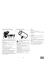
Always tighten the wheel nuts crosswise.
(1)
(6)
(3)
(4)
(2)
(5)
Please adhere stringently to the service
intervals stated.
Summary of Contents for XRVS 1350
Page 2: ......
Page 24: ... 24 FLOW DIAGRAM EXHAUST AFTERTREATMENT HPFP DOC EAM DPF ...
Page 30: ... 30 SH4 COMPRESSOR CIRCUIT 9822 0963 68 ...
Page 135: ......
Page 136: ......


