2.4.2.
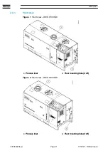
Side view
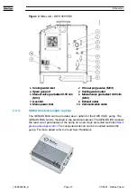
Figure 3
Side view - DWS 750 VSD+
1.
Cooling water inlet
2.
HV seal purge valve (MV3)
3.
Spare gas port
4.
Cooling water outlet
5.
Manual valve gas ballast 0
‑
50 slm
(MV1)
6.
Manual valve gas ballast 0
‑
80 slm
(MV2)
7.
Gas inlet
8.
Exhaust outlet
9.
Mains power inlet
10.
Communication cable
1.
Cooling water inlet
2.
HV seal purge valve (MV3)
3.
Spare gas port
4.
Cooling water outlet
5.
Manual valve gas ballast 0
‑
50 slm
(MV1)
6.
Manual valve gas ballast 0
‑
80 slm
(MV2)
7.
Gas inlet
8.
Exhaust outlet
9.
Mains power inlet
10.
Communication cable
Introduction
07/2021 - ©Atlas Copco
Page 12
1950840208_A


