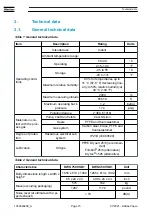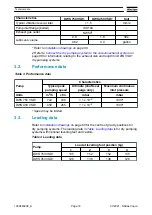
Table 6 Gas system flow option
Gas system type
Description
Valve
Gas flows (slm)
Total
flow
LV shaft
seal purge
HV shaft seal
purge
Balance
purge
Manually
adjusted gas
ballast
DWS 450 VSD+ *
DWS 750 VSD+ *
Gas ballast purge
(with manually ad-
justed flow) +
shaft seal purge
MV-3
position a
MV-1 off
MV-2 off
6
0.01
6
0
12
MV-1 on
MV-2 off
6
0.01
6
0-50
12-62
MV-1 off
MV-2 on
6
0.01
6
0-80
12-92
MV-1 on
MV-2 on
6
0.01
6
0-130
12-142
MV-3
position b
MV-1 off
MV-2 off
6
6
0.01
0
12
MV-1 on
MV-2 off
6
6
0.01
0-50
12-62
MV-1 off
MV-2 on
6
6
0.01
0-80
12-92
MV-1 on
MV-2 on
6
6
0.01
0-130
12-142
* The dry pumping systems in a standard configuration must run with a seal purge. If the purge free kit is equipped, this table is not
applicable.
07/2021 - ©Atlas Copco
Page 21
1950840208_A
Technical data

