background image

Serial Console Server User Manual

18

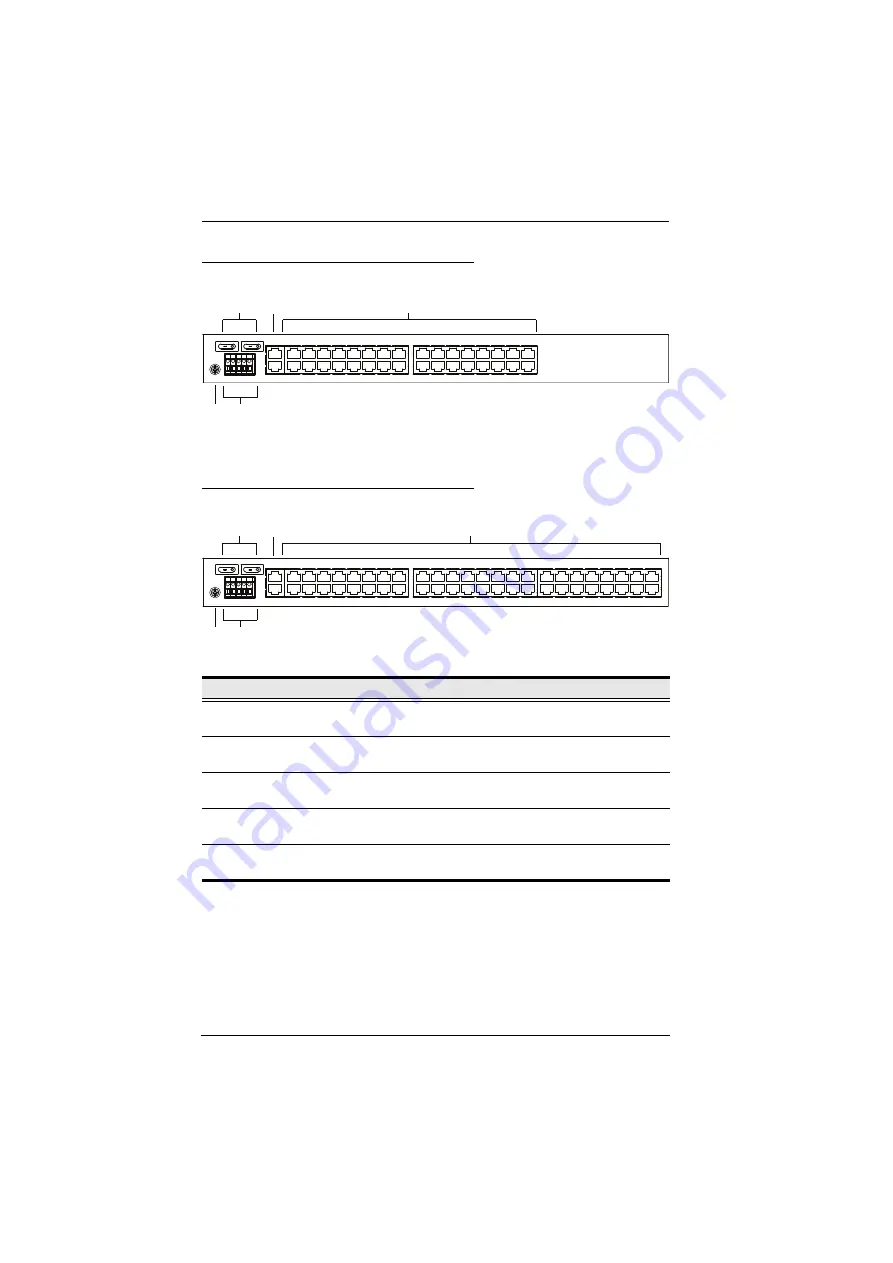
SN0132COD Rear View (DC Power)

SN0148COD Rear View (DC Power)

No.

Component

Description

1

Power 
Switches

These standard rocker switches power the unit on and off.

2

LAN Ports

The cables that connect the unit to the primary and the 
backup network interfaces (10/100/1000 Mbps) plug in here.

3

Serial Ports

The Cat 5e cables that connect to the serial devices or 
RJ45-to-Serial adapters plug in here. 

4

Grounding 
Terminal

The grounding wire that is used to ground the unit attaches 
here.

5

DC Terminal 
Block

The electric leads from your power source connect to this 
DC terminal block.

4

3

1

2

5

3

1

2

4

5

Summary of Contents for SN01 CO Series

Page 1: ...Serial Console Server SN0108CO SN0116CO SN0132CO SN0148CO SN9108CO SN9116CO SN0108COD SN0116COD SN0132COD SN0148COD User Manual www aten com...

Page 2: ...o communications Operation of this equipment in a residential area is likely to cause harmful interference in which case the user will be required to correct the interference at his own expense This d...

Page 3: ...ion if the battery is replaced with an incorrect type Dispose of used batteries according to the relevant instructions Batterie avis de s curit Il existe un risque d explosion si la batterie est rempl...

Page 4: ...s prove defective following their purchase the buyer and not the manufacturer its distributor or its dealer assumes the entire cost of all necessary servicing repair and any incidental or consequentia...

Page 5: ...Mounting Kit 2 Lok U Plugs 1 Lok U Plug Installation Tool 1 Foot Pad Set 4 pcs 1 User Instructions SN0108COD SN0116COD 1 SN0108COD SN0116COD Serial Console Server 1 Laptop USB Console Cable 1 Mounting...

Page 6: ...o download the most up to date version of the manual Check to make sure that all of the components are present and in good order If anything is missing or was damaged in shipping contact your dealer R...

Page 7: ...Terminology xiv Chapter 1 Introduction Overview 1 Features 3 System Accessibility and Availability 3 Serial Console Management 3 Security 4 System Management 4 Serial Device Management 5 Language 5 R...

Page 8: ...3 Super Administrator Setup Overview 33 First Time Setup 33 Local Login 33 Laptop USB Console LUC Login SNViewerUSB 34 Console Login HyperTerminal 34 Local Console Main Menu 35 Remote Login 36 Telnet...

Page 9: ...CP 56 TCP Client 57 UDP Mode 57 Virtual Modem 57 Console Management Direct 58 Disabled 58 Chapter 6 Port Access Overview 59 The Sidebar 60 The Sidebar Tree Structure 60 Filter 61 Connections 62 Telnet...

Page 10: ...missions under Group Settings 96 Chapter 8 Device Management Devices 97 General 97 Mounted Devices 98 Network 100 IP Installer 101 Service Ports 101 Network Configuration 102 ANMS 105 Event Destinatio...

Page 11: ...ions 145 SN0108CO SN0116CO 145 SN0108COD SN0116COD 146 SN0132CO SN0148CO 147 SN0132COD SN0148COD 148 SN9108CO SN9116CO 149 IP Address Determination 150 The Local Console 150 IP Installer 150 Browser 1...

Page 12: ...erial Console Server with each of the available access methods from a local console an Internet browser and Windows application AP programs Chapter 5 Port Operating Modes describes the port operating...

Page 13: ...r example Enter means to press the Enter key If keys need to be chorded they appear together in the same bracket with a plus sign between them Ctrl Alt 1 Numbered lists represent procedures with seque...

Page 14: ...er by a physical connection Servers Serial Device or Port Device any device attached to the Serial Console Server s ports via cable User s Point of View Local client users We refer to a user as a Loca...

Page 15: ...ess to servers and network devices via a direct Telnet SSH client and Java viewer The OOB management enables IT administrators to manage network devices e g router switch UPS in server rooms using man...

Page 16: ...ole Management Direct Real Com Port TCP Server Client UDP Server Client and Virtual Modem Furthermore the SN01xxCO Series works in tandem with ATEN s PDU see Note remote power management systems Both...

Page 17: ...ine Offline detection of connected serial devices including terminal blocks automatically send event notifications when the devices are offline for device status monitoring Convenient and simple seria...

Page 18: ...standards that use an embedded FIPS 140 2 certified OpenSSL cryptographic module Certificate 1747 2398 2473 System Management System configuration via web browser Telnet SSH client and local console...

Page 19: ...ver 2003 2008 Real TTY driver for Linux Fixed TTY driver for UNIX Supports baud rates of 300 600 1200 1800 2400 4800 9600 19200 28800 38400 57600 115200 230400 bps Language Multi language web based GU...

Page 20: ...ntime Environment JRE 8 or higher must be installed and at least 2MB of memory must be available after installation Java is available for free download from the Sun Java website http java sun com The...

Page 21: ...to Cisco switches and other compatible devices with straight through Cat 5e cables For serial port pin outs please refer to Pin Assignment on page 158 To connect to DB9 or DB25 device interface Seria...

Page 22: ...l Console Server User Manual 8 Browsers Supported browsers for logging into the device include the following Browser Version IE 11 and higher Chrome 70 and higher Firefox 63 and higher Safari 12 and h...

Page 23: ...t is powered up and ready to operate 2 Port LEDs The Port Flashes Green Active data is being transmitted through the port 3 LAN LEDs Primary and Secondary 10 100 1000 Mbps LAN LEDs RED 10 Mbps RED GRE...

Page 24: ...ives you the opportunity to try upgrading the firmware again Note This operation should only be performed in the event of a firmware upgrade failure that results in the device becoming inoperable 5 PO...

Page 25: ...rmation about their corresponding serial ports Lights Green Online the serial device attached to the port is powered on and ready Flashes Green Active data is being transmitted through the port 3 LAN...

Page 26: ...ves you the opportunity to try upgrading the firmware again Note This operation should only be performed in the event of a firmware upgrade failure that results in the device becoming inoperable 5 PON...

Page 27: ...rmation about their corresponding serial ports Lights Green Online the serial device attached to the port is powered on and ready Flashes Green Active data is being transmitted through the port 3 LAN...

Page 28: ...This does not clear User Account information See Clear Login Information page 157 for information on clearing user account information Pressing and holding this switch while powering on the switch ret...

Page 29: ...2 Power Switches These standard rocker switches power the unit on and off 3 LAN Ports The cables that connect the unit to the primary and the backup network interfaces 10 100 1000 Mbps plug in here 4...

Page 30: ...es that connect the unit to the primary and the backup network interfaces 10 100 1000 Mbps plug in here 3 Serial Ports The Cat 5e cables that connect to the serial devices or RJ45 to Serial adapters p...

Page 31: ...2 Power Switches These standard rocker switches power the unit on and off 3 LAN Ports The cables that connect the unit to the primary and the backup network interfaces 10 100 1000 Mbps plug in here 4...

Page 32: ...es that connect the unit to the primary and the backup network interfaces 10 100 1000 Mbps plug in here 3 Serial Ports The Cat 5e cables that connect to the serial devices or RJ45 to Serial adapters p...

Page 33: ...dard rocker switches power the unit on and off 3 Grounding Terminal The grounding wire that is used to ground the unit attaches here 4 LAN Port The cable that connect the unit to the network interface...

Page 34: ...Serial Console Server User Manual 20 This Page Intentionally Left Blank...

Page 35: ...he weight of its attached cables To place the device or to stack units if you are daisy chaining them remove the backing material from the bottom of the rubber feet that came with your package and sti...

Page 36: ...Serial Console Server User Manual 22 Note To ensure adequate ventilation allow at least 5 1 cm on each side and 12 7 cm behind the unit for power cord and cable clearance...

Page 37: ...k of the unit so that it can attach to the front or the back of the rack Rack Mounting Front To mount the unit at the front of the rack do the following 1 Remove the two screws at the front of the uni...

Page 38: ...al 24 3 Position the device in the front of the rack and align the holes in the mounting brackets with the holes in the rack 4 Screw the mounting brackets to the rack Note Cage nuts are provided for r...

Page 39: ...ove the two screws at the rear of the unit 2 Use the M3 x 8 Phillips head hex screws supplied with the rack mounting kit to screw the rack mounting brackets into the rear of the unit 3 Position the de...

Page 40: ...Serial Console Server User Manual 26 4 Screw the mounting brackets to the rear of the rack Note Cage nuts are provided for racks that are not pre threaded...

Page 41: ...Note Refer to DB 9 DB 25 Interface on page 159 for pin assignments 3 Connect a Cat 5e cable between a Cisco Network Switch or any compatible network switch and any available RJ 45 port on the Serial...

Page 42: ...ou are using a laptop USB console to control the Serial Console Server locally use the laptop USB console cable included in the package to connect the laptop to the LUC port on the Serial Console Serv...

Page 43: ...e ports and switches but with slightly different layouts See Components page 9 for details 7 8 9 5 6 4 10 11 2 3 1 Modem ATEN PDU Cat5 PC COM Cisco Console Cable USB LUC Laptop Cisco Console Cable Nul...

Page 44: ...45 port on the Serial Console Server s rear panel Note Refer to DB 9 DB 25 Interface on page 159 for pin assignments 3 Connect a Cat 5e cable between a Cisco Network Switch or any compatible network s...

Page 45: ...Chapter 2 Hardware Setup 31 SN9108CO SN9116CO Installation Diagram...

Page 46: ...Serial Console Server User Manual 32 This Page Intentionally Left Blank...

Page 47: ...NViewerUSB application SN0108CO SN0116CO SN0132CO SN0148CO only Setup can also be done remotely over the Web via the GUI using the unit s IP address Note For remote methods of setting up the network s...

Page 48: ...ed and you will be prompted to log in as shown here Since this is the first time you are logging in use the default Username administrator and the default Password password Console Login HyperTerminal...

Page 49: ...ng in use the default Username administrator and the default Password password Local Console Main Menu After you log in via HyperTerminal or SNViewerUSB the text based menu appears The Main Menu is th...

Page 50: ...s you work your way through the text sub menus and configure the settings discussed in this chapter Telnet Login Start Telnet type open 192 168 0 60 press Enter and a login prompt will appear as show...

Page 51: ...sole Server in the browser s location bar and press Enter 2 When a Security Alert dialog box appears accept the certificate it can be trusted Once you accept the certificate s the login page appears 3...

Page 52: ...ver User Manual 38 Setup Network Setup To set up the network do the following 1 Click the Device Management tab 2 Select the Network tab 3 Fill in the fields according to the information provided unde...

Page 53: ...list of Users and Groups in the Sidebar at the left and a more detailed list of users with more information about them in the large central panel Since this is the first time the page is being accesse...

Page 54: ...nual 40 4 Enter the password again in the Confirm Password field to confirm it is correct 5 Click Save located at the bottom of the page 6 When the dialog box informing you that the change completed s...

Page 55: ...e computer using Telnet SSH PuTTY or web based browser see First Time Setup page 33 for details No matter which access method you choose the Serial Console Server s authentication procedure requires y...

Page 56: ...n provided for the browser version as you work your way through the sub menus Note 1 As with the browser version access to many of these sub menus are restricted by the user s permissions If you selec...

Page 57: ...onsole Server do the following 1 Open the browser and specify the IP address See Browser Login page 37 for details of the Serial Console Server you want to access in the browser s location bar 2 When...

Page 58: ...Bar The tab bar contains the Serial Console Server main operation categories The items that appear in the tab bar are determined by the user s type and the authorization options that were selected wh...

Page 59: ...out Click this button to log out of your Serial Console Server session 6 Welcome Message If this function is enabled see Welcome Message page 67 a welcome message displays here 7 Interactive Display P...

Page 60: ...e been given User Management permission The tab doesn t appear for other administrators and users User Management is discussed on page 81 Device Management The Device Management page is used to config...

Page 61: ...n at the upper center of the screen and becomes visible when your mouse moves over it The panel consists of three rows an icon row at the top and two text rows below it By default the upper text row s...

Page 62: ...ing off This starts a log file of characters sent from the serial device to the SNViewer You must first create and import a text based log file See Terminal Settings Others Log File page 53 Use this t...

Page 63: ...to its default settings Click to bring up the Message Board see The Message Board page 50 Click to open a window and create a list of custom text macros see Macros page 51 Use this to change the font...

Page 64: ...ns which may cause access conflicts To alleviate the problem a message board has been provided which allows users to communicate with each other Message Display Panel Messages that users post to the b...

Page 65: ...rs Simply check a box type in the text macro and click Save Use the associated function key F1 F12 to run the custom text macro s you created Terminal Application You can log in remotely using a text...

Page 66: ...right side of the window you can view an example of the font you have set Color Select an Option Foreground color Background Color Cursor Text color or Cursor Color and Click Change to adjust the col...

Page 67: ...echoed but not displayed on the screen Force On Characters that are typed in are echoed and displayed on the screen as they are entered Passwords are displayed on the screen if this mode is used Force...

Page 68: ...te Login page 36 for details The Telnet and PuTTY Main Menus are the text based equivalent of the browser based configuration and control functions described throughout this manual You can reference t...

Page 69: ...ial to Ethernet connectivity and applications that require COM ports serial tunneling or where TCP UDP Socket functionality is needed An explanation of the functions performed by the various operating...

Page 70: ...mode is used in conjunction with a virtual COM port driver installed on the remote user s local computer When the Serial Console Server s COM port is set to this mode the device connected to the port...

Page 71: ...to the to the host The Serial Console Server can send data to up to 16 host computers simultaneously and supports 128 bit 256 bit SSL TLS v1 0 TLS v1 1 TLS v1 2 data encryption in this operating mode...

Page 72: ...bit SSL TLS v1 0 TLS v1 1 TLS v1 2 data encryption is supported in this operating mode Console Management Direct In this mode users establish a Telnet or SSH session directly from a PC to a server or...

Page 73: ...splayed The Connections page is organized into several main areas All the devices ports and outlets that a user is permitted to access are listed in the Sidebar at the left of the page After selecting...

Page 74: ...the Sidebar tree structure are Users are only allowed to see the devices and ports that they have access permission for Ports become green to show that the serial device is online Ports become green...

Page 75: ...of the choices are explained in the following table Choices Explanation Search If you key in a search string and click Search only port names that match the search string display in the tree Wildcard...

Page 76: ...by a user through the Serial Console Server Operation Mode This column lists the Work Mode that the port is set to for access The most common setting is Console Management which is set on the Port Ac...

Page 77: ...the serial device and a screen similar to the one below appears From the SNViewer can you login and perform management activities on the serial device For more information on using the SNViewer see S...

Page 78: ...Serial Console Server User Manual 64 From here you can use the Telnet SSH and Dump Buffer buttons at the bottom of the page...

Page 79: ...ound on the Port List tab See Connections page 62 for details History The History page provides a record of each time that a port was accessed It provides quick access to the most recently used ports...

Page 80: ...s automatically logged out Once logged out a login is necessary before the Serial Console Server can be accessed again Broadcast Timeout If there is no user input for the amount of time set here the B...

Page 81: ...ult is disabled Broadcast Ports Select the ports to receive broadcast commands by selecting the boxes Selecting Broadcast Ports allows you to access and make changes on a single port and the same chan...

Page 82: ...ports and PDU devices The Access page only appears for those users with User Management permissions and is not available for other users Access rights can be set on a user by user or a group by group...

Page 83: ...nd configuration rights of each Group Access Rights The Access columns are where access rights are set The meaning of each is explained below Full Access The user can view the device and can perform o...

Page 84: ...rt Settings List or from the Sidebar the Properties page appears and looks similar to the one below This panel allows you to make configuration settings for the selected port as explained in the table...

Page 85: ...ransmit one character of data Choices are 5 6 7 and 8 Set this to match the data bit setting of the connected device Default is 8 which is a default setting for many serial devices Parity This bit che...

Page 86: ...Note USB drive is only supported on SN01xxCO models To enable Port Buffering from the drop down menu select Memory NFS Syslog Server or select a mounted USB drive Select Disable to disable Port Buffer...

Page 87: ...he most common setting is Console Management which allows for Telnet SSH sessions from the Port Access Connections page Select the port s work mode from the drop down menu Note See Port Operating Mode...

Page 88: ...ultaneously share control over the port Input from the users is placed in a queue and executed chronologically Occupy Timeout If there is no input on this port for the amount of time set with this fun...

Page 89: ...l Console Server receives such a message it can send an SNMP Trap alert and or an email to inform the user specified here of the problem You can specify up to 10 types of alerts After setting up this...

Page 90: ...ng the TCP connection to the host computer Inactivity Time This setting defines how long to wait when there is no data transfered between the Serial Console Server and host computer before the connect...

Page 91: ...ransfered through the session Destination Host Port Key in the IP address and service port of Destination Host or another Serial Console Server TCP Server to create a serial tunnel for transmitting th...

Page 92: ...odem Check Enable to encrypt all data being transfered through the session Setting Meaning Host Start IP Host End IP and Port Use this setting to establish connections via the UDP protocol Enter a sin...

Page 93: ...ut box port control is transferred to the next user who makes a change on the system Share Users simultaneously share control over the port Input from the users is placed in a queue and executed chron...

Page 94: ...g the Alert Strings and Command Filters see page 74 Disabled Select this option to disable use of the serial port on the Serial Console Server CRLF Translation This allows you to select whether to sen...

Page 95: ...of the page The large panel at the right provides more detailed information at a glance for each The Browser GUI has separate menu bar entries for Accounts Users and Groups Depending on the menu item...

Page 96: ...ser tab selected User Type Role Super Administrator Access and manage ports and devices Manage Users and Groups Configure the overall installation Configure personal working environment Administrator...

Page 97: ...be altered The Administrators default permissions include everything except Device Admin and User Admin but the permissions can be altered for each Administrator by checking or unchecking any of the...

Page 98: ...pe of the account select Account never expires if you do want to limit the amount of time that the account remains in effect select Account expires on and key in the expiration date To require a user...

Page 99: ...ed band The large main panel shows the user s name the description that was given when the account was created and whether the account is currently active or has been disabled Modifying User Accounts...

Page 100: ...ors need only set them once for the group instead of having to set them for each user individually Multiple groups can be defined to allow some users access to specific devices while restricting other...

Page 101: ...main panel The Sidebar Group list can expand and collapse If the list is expanded click the minus symbol next to the Users icon to collapse it if it is collapsed there is a plus symbol next to the ic...

Page 102: ...name 2 Click Modify 3 In the Group notebook that comes up make your changes then click Save Note The Group page is discussed on page 86 the Members page is discussed on page 92 The Devices page is di...

Page 103: ...s to a Group From the User s Notebook To assign a user to a group from the User s notebook do the following 1 In the Sidebar User list click the user s name or In the main panel select the user s name...

Page 104: ...epeat the above for any other groups that you want the user to be in 7 Click Save when you are done Note If a user has permissions in addition to the ones assigned to the group the user keeps those pe...

Page 105: ...e user s name 2 Click Modify 3 In the User notebook that comes up select the Groups tab A screen similar to the one below appears 4 In the Selected column select the group that you want to remove the...

Page 106: ...ook that comes up select the Members tab A screen similar to the one below appears 4 In the Available column select the user that you want to be a member of the group 5 Click the Right Arrow to put th...

Page 107: ...he group s name 2 Click Modify 3 In the Group notebook that comes up select the Members tab A screen similar to the one below appears 4 In the Selected column select the user that you want to remove f...

Page 108: ...e ports and the devices connected to them are assigned on a port by port basis from the User or Group list on the Sidebar of the User Management page Assigning Device Permissions under User Settings T...

Page 109: ...iew the remote screen and can perform operations on the remote server from his keyboard View Only The user can only view the remote screen he cannot perform any operations on it No Access No access ri...

Page 110: ...t the group s name 2 Click Modify 3 In the Groups notebook that comes up select the Devices tab 4 The screen that comes up is the same one that appears in the User s notebook The only difference is th...

Page 111: ...k configurations Note The MFG Number Manufacturing Number is an internal serial number used by ATEN s factory and technical support staff to identify products This number does not affect products warr...

Page 112: ...warning temporarily With this method the warning function will be back in effect after the next system reset Mounted Devices The Mounted Devices section displays information about USB and NFS storage...

Page 113: ...Unmount to mount or unmount the drive The Status column indicates N A Mounted or Unmounted Syslog Settings for Port Logs You can allow users to store logs on pre defined Syslog servers To activate th...

Page 114: ...Network page is used to specify the network environment Each of the elements on this page is described in the sections that follow Note The Enable Redundant NIC option is only available for SN0108CO...

Page 115: ...l will allow If a port other than the default is used users must specify the port number as part of the IP address when they log in If an invalid port number or no port number is specified the Serial...

Page 116: ...he listbox is disabled you cannot configure eth1 3 Configure the IP and DNS server addresses for eth0 see the sections below Redundant NIC Not Enabled Two IP Addresses If you choose not to enable the...

Page 117: ...the unit starts up it waits to get its IP address from the DHCP server If it hasn t obtained the address after one minute it automatically reverts to its factory default IP address 192 168 0 60 61 2 I...

Page 118: ...o button This is the default setting To specify a fixed IP address select the Set IP address manually radio button and fill in the fields with values appropriate for your network DNS Server For automa...

Page 119: ...ow Event Destination SMTP Settings To have the Serial Console Server email reports from the SMTP server to you do the following 1 Enable the Enable report from the following SMTP server and key in eit...

Page 120: ...emicolon The total cannot exceed 256 Bytes Log Server Important transactions that occur on the Serial Console Server such as logins and internal status messages are kept in an automatically generated...

Page 121: ...he computer s to be notified of SNMP trap events The valid port range is 1 65535 The default port number is 162 Note Make sure that the port number you specify here matches the port number used by the...

Page 122: ...nge is 1 65535 SMS Settings To receive notifications via SMS do the following 1 Check Enable 2 Enter the telephone numbers for the Message Center and SMS Receiver Note When you have made all your chan...

Page 123: ...e Retries field set the number of allowed RADIUS retries 5 In the Shared Secret field key in the character string that you want to use for authentication between the Serial Console Server and the RADI...

Page 124: ...he LDAP Server field For LDAP the default port number is 389 for LDAPS the default port number is 636 Alternate LDAP Server and Alternate LDAP Service Port Fill in the IP address and port number for t...

Page 125: ...chema Only Groups in AD are matched User privileges are the ones configured for the groups he belongs to on the Serial Console Server Without schema Usernames and Groups in AD are matched User privile...

Page 126: ...Serial Console Server User Manual 112 Kerberos Enable Kerberos and enter the following information Kerberos Server Kerberos Service Port Kerberos Realm...

Page 127: ...and fill in the CC Server s IP address and Service port in the appropriate fields You can use the IPv4 address the IPv6 address or the domain name in the CC Server IP field Note If this function is e...

Page 128: ...nual 114 OOBC In case the Serial Console Server cannot be accessed with the usual LAN based methods it can be accessed via the Serial Console Server s modem port or one of the serial ports SN9108CO SN...

Page 129: ...Chapter 8 Device Management 115 SN0108CO SN0116CO SN0132CO SN0148CO...

Page 130: ...Serial Console Server User Manual 116 SN9108CO SN9116CO Select the Port Number that the Console PON reserved and Modem is connected to on the rear of the SN9108CO SN9116CO...

Page 131: ...oming call the Serial Console Server hangs up the modem and dials back to the modem whose phone number is specified in the Phone Number field Key the phone number of the modem that you want the Serial...

Page 132: ...he Serial Console Server reconnects to it If you choose PPP online time the connection to the ISP will terminate after the amount of time that you specify is up A setting of zero means it is always on...

Page 133: ...es with no restrictions For security purposes we recommend that you enable this function and enable the lockout policies Entry Explanation Login Fail Policy This determines what happens when a user fa...

Page 134: ...redirect HTTP to HTTPS HTTPS TLS v1 0 1 1 1 2 SNMP Agent ICMP Default 4 Custom Click to check the following security options you wish to apply Enable Telnet service Enable SNMP Agent service Enable IC...

Page 135: ...To enable IP and or MAC filtering select one of the following radio buttons If the Include button is selected all the addresses within the filter are allowed access all other addresses are denied acce...

Page 136: ...C filter in other words if a computer s address is allowed by one filter but blocked by the other then the blocking filter takes precedence the computer s access is blocked Modifying Filters To modify...

Page 137: ...d Users can log in with only a Username The default is 6 Password Must Contain At Least Checking any of these items requires users to include at least one uppercase letter one lowercase letter or one...

Page 138: ...Serial Console Server User Manual 124 Association The Association tab is currently reserved...

Page 139: ...e switch is currently set to The time and date fields are for information purposes and cannot be edited Note In the Browser UI the system time displays the time relative to the time zone that the web...

Page 140: ...ing on the selected interface language To have the time automatically synchronized to a network time server select the Synchronize with NTP server radio button If you want to use your network s defaul...

Page 141: ...ge the sort order of the display by clicking on the column headings The log file tracks a maximum of 512 events When the limit is reached the oldest events get discarded as new events come in The purp...

Page 142: ...rds in the log file Range Select this radio button to filter results for records for a particular time period then click the From and To fields and a calendar will appear for you to select the dates P...

Page 143: ...adio button for the severity level that you want to display All Most Less or Least Only events that match the severity level you specified appear in the display Apply Click to apply the filter choices...

Page 144: ...notifications are grouped into five groups You can choose to enable the following All system events All authentication events All user management events All device management events All system task e...

Page 145: ...backup and restore configuration and account information and restore default values Backup Restore When you click on the Maintenance tab it opens with the Backup Restore page This page gives you the a...

Page 146: ...hen the browser asks what you want to do with the file select Save to disk then save it in a convenient location Restore To restore a previous backup do the following 1 Click Browse navigate to the fi...

Page 147: ...ry that the new firmware file is in and select the file 4 Click Upgrade Firmware to start the upgrade procedure If you enabled Check Firmware Version the current firmware level is compared with that o...

Page 148: ...igned certificate and importing a third party certificate authority CA signed certificate Generating a Self Signed Certificate If you wish to create your own self signed certificate a free utility ope...

Page 149: ...ertificate page shown here 2 Click Browse to the right of Certificate Filename and browse to where your certificate file is located and select it 3 Click Import to complete the procedure Note Clicking...

Page 150: ...ries that are valid for your site according to the example information in the following table Information Example Country 2 letter code TW State or Province Taiwan Locality Taipei Organization Your Co...

Page 151: ...ate save it to a convenient location on your computer 6 Click Import from the lower menu bar and the Private Certificate window pops up as shown here 7 Click Choose File to locate the certificate and...

Page 152: ...Serial Console Server User Manual 138 This Page Intentionally Left Blank...

Page 153: ...been provided Never spill liquid of any kind on the device Unplug the device from the wall outlet before cleaning Do not use liquid or aerosol cleaners Use a damp cloth for cleaning Avoid circuit ove...

Page 154: ...ing power to hot pluggable power supplies observe the following guidelines Install the power supply before connecting the power cable to the power supply Unplug the power cable before removing the pow...

Page 155: ...x 141 Only adjust those controls that are covered in the operating instructions Improper adjustment of other controls may result in damage that will require extensive work by a qualified technician to...

Page 156: ...ns must be met This equipment shall be connected directly to the DC supply system earthing electrode conductor or to a bonding jumper from an earthing terminal bar or bus to which the DC supply system...

Page 157: ...r out of a rack the slide rails can pinch your fingers After a device is inserted into the rack carefully extend the rail into a locking position and then slide the device into the rack Do not overloa...

Page 158: ...orehand Product model number serial number and date of purchase Your computer configuration including operating system revision level expansion cards and software Any error messages displayed at the t...

Page 159: ...Power 2 x Rocker Switch LEDs Serial Port Status 8 Green 16 Green 10 100 1000 Mbps 2 Red Orange Green Power 2 Blue I P Rating AC 100 240V 50 60Hz 1A Power Consumption 110V 14 1W 220V 14W 110V 15 4W 22...

Page 160: ...Reset 1 x Recessed Pushbutton Power 2 x Rocker Switch LEDs Serial Port Status 8 Green 16 Green 10 100 1000 Mbps 2 Red Orange Green Power 2 Blue I P Rating DC 36 48 V DC 1 6 A in 5 Pin Terminal Block P...

Page 161: ...Pushbutton Power 2 x Rocker Switch LEDs Serial Port Status 32 Green 48 Green 10 100 1000 Mbps 2 Red Orange Green Power 2 Blue I P Rating AC 100 240V 50 60Hz 1 8A Power Consumption 110V 20 2W 220V 21W...

Page 162: ...e Switches Reset 1 x Recessed Pushbutton Power 2 x Rocker Switch LEDs Serial Port Status 32 Green 48 Green 10 100 1000 Mbps 2 Red Orange Green Power 2 Blue I P Rating DC 36 48 V DC 1 6 A in 5 Pin Term...

Page 163: ...Mbps 1 Red Orange Green Power 1 Blue I P Rating AC 100 240V 50 60 Hz 1A Power Consumption 110V 9 7W 220V 9 6W 110V 10 9W 220V 11 6W Mode of Operation Console Management Console Management Direct Real...

Page 164: ...100 The Local Console The easiest way to assign an IP address is from the local console Refer to First Time Setup page 33 for details on the procedure involved IP Installer For client computers runni...

Page 165: ...ields with the information appropriate to your network 5 Click Set IP 6 After the IP address shows up in the Device List click Exit See IP Installer page 101 for more information Browser 1 Set your cl...

Page 166: ...l list box see page 97 Once you have determined what the IPv6 address is you can use it when logging in from a browser or the Win and Java Client AP programs For example If you are logging in from a b...

Page 167: ...ss For example 2001 74ff fe6e 59 As above the address is displayed in the General list box of the Device Management Device Information page see page 97 Once you have determined what the IPv6 address i...

Page 168: ...K CR LF If failure ERROR CR LF ATH CR Hang up current TCP connection if a connection is active Note ATH ATH0 and ATH1 all act the same If successful OK CR LF If failure ERROR CR LF ATIn CR Inquiry com...

Page 169: ...uses the modem to switch to command mode without disconnecting D2 DTR OFF switches modem to command mode hangs up and disables auto answer Default D3 DTR OFF initializes the modem If successful OK CR...

Page 170: ...er s setup program and access the Port Forwarding sometimes referred to as Virtual Server configuration page You would then specify 192 168 1 180 for the IP address and the port number you want opened...

Page 171: ...he following 1 Power off the Serial Console Server and remove its housing 2 Use a jumper cap to short the mainboard jumper labeled J11 for SN0132CO SN0148CO as shown in the diagram below or J17 for SN...

Page 172: ...nect directly to Cisco network switches and other compatible devices The pin assignment for the serial ports under different mode is shown below DCE Mode Pin Assignment DTE Mode Pin Assignment Pin Def...

Page 173: ...o the tables below DB 9 DB 25 RJ 45 Pin Signal DB 9F Pin Signal 1 CTS 7 RTS 2 DSR 4 DTR 5 GND 3 RxD 3 TxD 4 GND 5 GND 6 TxD 2 RxD 7 DTR 1 GND 6 DSR 8 RTS 8 CTS RJ 45 Pin Signal DB 25F Pin Signal 1 CTS...

Page 174: ...EN will provide a repair service without charge during the Warranty Period If a product is detective ATEN will at its discretion have the option to 1 repair said product with new or repaired component...

Reviews: