ATEN Altusen KN9000 User Manual Download Page 36

36

5. Do not click OK

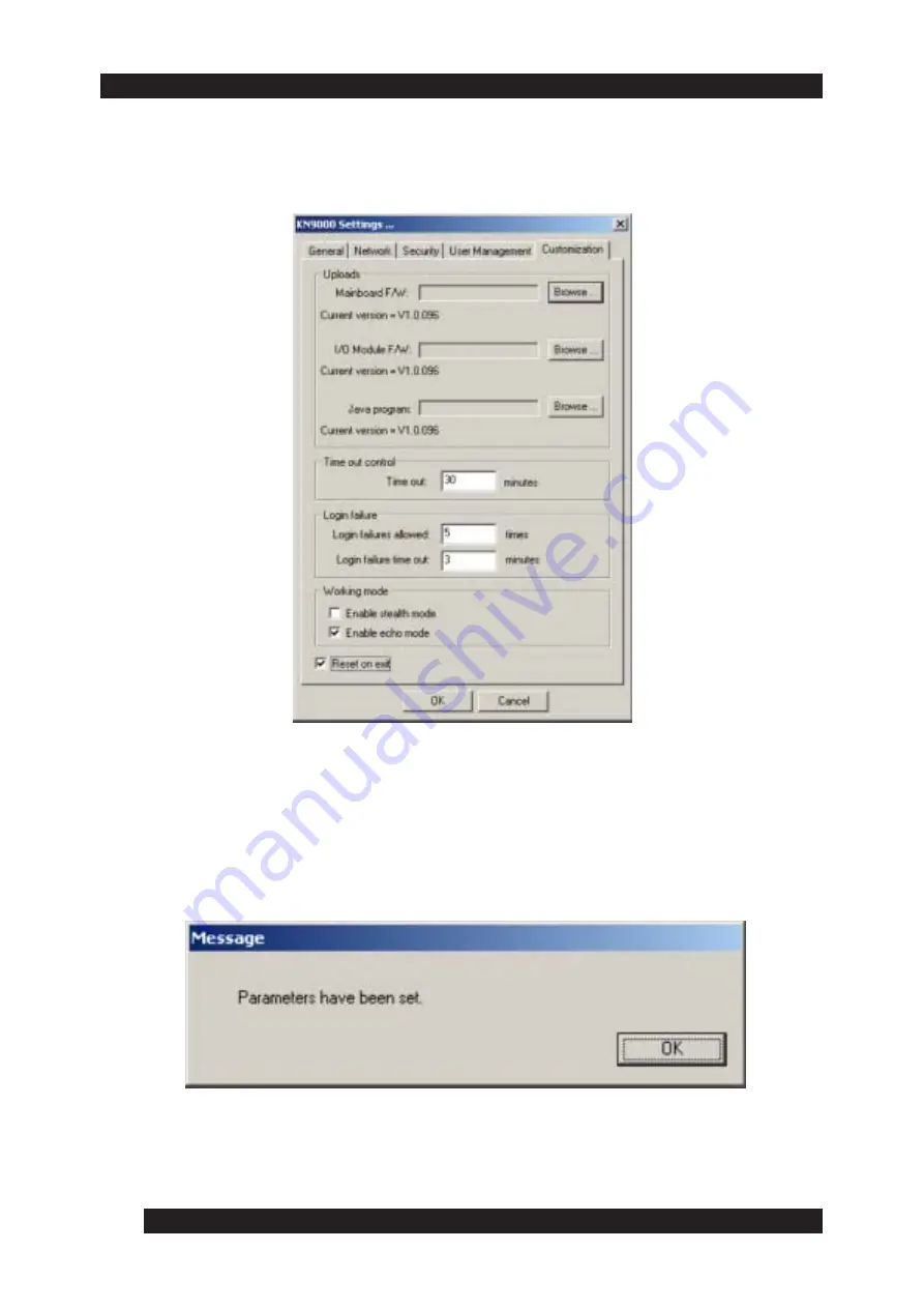
 or press [Enter] Click the 

Customization

 tab to display its

   settings (see figure below).

6. Click the 

Reset on Exit

 checkbox to toggle on and then click 

OK

. The

    following message window appears, alerting you that 

Parameters have

     been set:

Summary of Contents for Altusen KN9000

Page 1: ...1...

Page 2: ...2...

Page 3: ...against harmful interference when the equipment is operated in a commercial environment This equipment gen erates uses and can radiate radio frequency energy and if not installed and used in accordan...

Page 4: ...4...

Page 5: ...irements Chapter 2 Hardware Setup Components Hardwareinstallation Chapter 3 The Administrator Utility Installing the Administrator Tool Uninstall Gettingstarted Loggingin TheSettingswindow General Net...

Page 6: ...ity Chapter 5 The Java Client InstallingtheJavaclient Gettingstarted OperatingtheKN9000remotewindow Theuserpanel Videoadjustment Keypad Mousesynchronization Screennavigation Exit RemotekeyboardLEDs Ch...

Page 7: ...7 Appendix A Specifications Appendix B Stacking and Mounting Appendix C LimitedWarranty 93 95 97...

Page 8: ...e installation and use of the administrator tools that conifigure and manage your system Chapter 4 The Windows Client details the operations performed by the Windows based client software Chapter 5 Th...

Page 9: ...and emphasized words Indicates a key to press on your keyboard Alt press the Alt key Alt Ctrl press the Alt and Control keys at the same time Alt Ctrl Del press the Alt and Control keys at the same t...

Page 10: ...USEN support website http www altusen com support Troubleshooting Online troubleshotting describes some of the most commonly encountered problems and provides possible solutions Visit the ALTUSEN supp...

Page 11: ...t model number serial number and date of purchase Your current computer configuration including operating system revision level add on boards and software Error messages displayed at the time the erro...

Page 12: ...12...

Page 13: ...TCP IP as its communication protocol network administrators can remotely access attached KVM switches allowing remote control of the attached servers to perform many tasks with ease and speed such as...

Page 14: ...ystems The Log Server records all the events that take place on selected KN9000 units for the administrator to analyze Once an operator successfully connects and logs in a screen appears displaying ev...

Page 15: ...ation Card Check to make sure that each item in the above list is included in your package If an item is missing or damaged in shipment please contact your dealer System Requirements To use and access...

Page 16: ...le position and disable Enhance Pointer Precision Windows 2000 set the mouse speed to the middle position and select None for mouse acceleration Windows NT 98 set the mouse speed to the slowest positi...

Page 17: ...corresponds to a number in the list that follows The front panel of the KN9000 contains the following components 1 Reset Switch Press this switch to the in position to perform a system reset NOTE Thi...

Page 18: ...r panel of the KN9000 contains six features as shown in the figure below Each number in the figure corresponds to a number in the list that follows The rear panel of the unit contains the following co...

Page 19: ...h port The administrator uses this console to access the server or KVM switch connected to the KN9000 6 KVM Port Section The KVM cable that links the KN9000 to the server or KVM switch plugs into the...

Page 20: ...witch 2 is set to the ON position by default Switch 3 is used to either limit KN9000 access to software with a matching serial number software provided in the same package or provide access to softwar...

Page 21: ...electric discharge properly ground all devices on the installation Consult your dealer for technical details if necessary 1 Plug the local administrator s keyboard mouse and monitor into the unit s C...

Page 22: ...nto the KN9000 s RJ 45 socket and connect the other end of the cable to the network The network connection may be a hub switch or router 4 Plug one end of the power cord into the KN9000 s power socket...

Page 23: ...23 5 Power up your server or KVM installation 6 Power up the KN9000...

Page 24: ...24...

Page 25: ...ROM drive Complete one of the following Open the drive letter that corresponds to the CD ROM Open the file folder containing the Administrator Tool Setup icon and double click the Administrator Tool S...

Page 26: ...nel Add Remove Programs NOTE Your system s Control Panel may be located in a different location depending on your operating system 3 Select the Administrator Tool from the list 4 Click Remove or Unins...

Page 27: ...r and enter again The Administrator Tool attempts to find all the KN9000 devices installed on the local LAN segment Once the Administrator Tool has finished searching for KN9000 devices the following...

Page 28: ...address and Port number in the KN9000 address and Port fields and then click Login Logging In Once the Administrator Tool connects to the specified unit the login window appears Only users with config...

Page 29: ...esses the login request and the following message window appears 3 The first time you log in to KN9000 a message window appears see figure below alerting you to change your user name and password Clic...

Page 30: ...The following section provides you with a description of each function and corresponding configuration information General The General page of the KN9000 Settings window see figure below provides you...

Page 31: ...llations by assigning each KN9000 a unique name To assign a name for a particular KN9000 delete the current name and type in a new name with a maximum of 15 characters Main firmware version Indicates...

Page 32: ...tor can set the Port number that a user must specify while attempting to connect to a KN9000 s IP address If an incorrect Port number is given the KN9000 device cannot be found A description of the Pr...

Page 33: ...ss field specify a MAC address and Port number for the server where you want the log file to reside For additional information on the Log Server see Chapter 6 Typical Network Configurations The follow...

Page 34: ...o the firmware see figure below The new IP address appears in the KN9000 devices list 1 Select Obtain an IP address automatically in the IP Address pane and then click OK to begin the update process 2...

Page 35: ...l window log in using the current IP address listed in the KN9000 devices list 2 The KN9000 Settings window appears Click the Network tab to display its settings 3 Select Set IP address manually in th...

Page 36: ...ress Enter Click the Customization tab to display its settings see figure below 6 Click the Reset on Exit checkbox to toggle on and then click OK The following message window appears alerting you that...

Page 37: ...es list 8 Click Refresh to update the KN9000 devices list with the new IP address you specified see figure below Security You can use the Security page of the KN9000 Settings window see figure below t...

Page 38: ...page that the user connects to when using the Java client to access the KN9000 Access to the KN9000 via the Java client is restricted to those users who know the specified page name A user cannot acce...

Page 39: ...he following options Click the IP filter enable checkbox to toggle on Click the MAC filter enable checkbox to toggle on 2 To Add a filter complete one or both of the following options To add an IP fil...

Page 40: ...e only addresses within the specified filter range are allowed access to the KN9000 If you select exclude only addresses with the specified filter range cannot access the KN9000 To delete a User Stati...

Page 41: ...window see figure below you must save these settings in order for the filters to take effect To add an Admin Station Filter 1 Click Add to the right of the Admin Station Filters list box The MAC addre...

Page 42: ...essage window appears see figure below alerting you that Parameters have been set 2 Click OK to return to the Administrator Tool window 3 Login again to view the filters you previously set up in the S...

Page 43: ...ow The User Management window appears see figure below User Management The User Management page see figure below of the KN9000 Settings window provides you with the ability to manage user profiles You...

Page 44: ...formation to further identify a user for administrator purposes Permissions by default all users may access the system through the Windows client software Select Java client to allow a client access t...

Page 45: ...e you sure to remove user username 3 Click OK when you have finished entering valid user information and setting permissions In the example shown in the above figure clicking OK provides Username mary...

Page 46: ...user name in the User List of the User Management page The user name appears highlighted 2 Click Edit The User Management window appears 3 Make the desired changes and then click OK In the example sh...

Page 47: ...ministrator to upgrade mainboard and I O firmware as well as Java contents In addition an administrator can set the timeout and login failure parameters The Customization page includes five panes see...

Page 48: ...od of time KN9000 ends the current connection is becomes available for other users Login failure Provides a security feature that prevents a user from making continuous log in attempts to access a KN9...

Page 49: ...d I O firmware and Java software NOTE Download new versions of the mainboard and I O firmware and Java software at http www altusen com While the following steps show you how to upload mainboard firmw...

Page 50: ...k Open You return to the Customization page The Mainboard F W field displays the file location as shown in the figure below NOTE If you select an incorrect file type for the component you want to upgr...

Page 51: ...e out control The Time out control pane allows more efficient and secure use of the KN9000 For example if the KN9000 receives no input for a specified amount of time the KN9000 ends the current connec...

Page 52: ...de pane is a security feature that controls how the KN9000 responds to KN9000 software searching for the KN9000 unit on the network You can select from one or both of the following two modes Enable St...

Page 53: ...nto the appropriate CD ROM drive Complete one of the following Open the drive letter that corresponds to the CD ROM Open the file folder containing the Windows Client Setup icon and double click the W...

Page 54: ...dows Client software follow these steps 1 Close all applications 2 Select Start Settings Control Panel Add Remove Programs NOTE Your system s Control Panel may be located in a different location depen...

Page 55: ...rst time the Serial Number window appears see figure below 2 Enter your assigned serial number 5 characters per field and then click OK If you do not know your serial number contact your system admini...

Page 56: ...56 The Connection Window After initiating the Windows Client the Connection window appears as shown below...

Page 57: ...ished the KN9000 name IP address and status appear in the KN9000 List KN9000 IP Allows you to connect to a remotely located KN9000 unit Use the drop down list to select an existing IP address or enter...

Page 58: ...type a valid IP address and port number in the KN9000 IP pane and then click Connect The Login window appears see figure below 2 Type a valid User Name and Password in the appropriate fields and then...

Page 59: ...00 View button activates once a connection is established To take over console control of the unit connected to the KN9000 click the Switch to KN9000 View button The remote computer displays on screen...

Page 60: ...icon For computers running XP or Win 2000 the keyboard LED status also displays as shown below NumLock CapsLock ScrollLock For computers running Win 98 or Win ME the KN9000 controls the LEDs on the ac...

Page 61: ...f keyboard video and mouse actions When a remote system s output is displayed on your local screen you can control the remote system with five Hotkeys To view the default HotKey combinations click the...

Page 62: ...l screen Adjust Video Displays the Video Options window allowing you to adjust the location and picture quality of the remote screen displayed on your local monitor Adjust Mouse Allows you to synchron...

Page 63: ...video resolution If mouse movements are no longer in sync with the remote system s mouse pointer you can synchronize them at any time by synchronizing the local and remote video screens The following...

Page 64: ...pointers If auto synching doesn t solve the problem check the mouse speed and acceleration settings for the computer or computers via KVM switch connected to the KN9000 Make certain they are set as r...

Page 65: ...nter Options Set the mouse speed to the middle position and disable Enhance Pointer Precision as shown below WinMe Win95 Set the mouse speed to the middle position and disable mouse acceleration WinNT...

Page 66: ...use the arrows to adjust the position of the remote window Auto Sync select Auto Sync to automatically detect the vertical and horizontal offset values for the remote screen You can also use Auto Sync...

Page 67: ...ch as a fiber optic cabling drag the slider bar towards High Drag the slider bar towards Low if your network is based on slow phone lines KN9000 uses this setting as the criteria to determine what nee...

Page 68: ...ys field 5 When you have finished entering your Function key sequence click Stop 6 To save the Function key sequence click Set 7 Repeat steps 2 through 6 for all actions you wish to set up When you ha...

Page 69: ...so includes information about how to connect to the KN9000 and remotely control the connected server or servers via a KVM switch Installing the Java Client To install the Java Client follow these step...

Page 70: ...t time the Serial Number window appears see figure below 2 Enter your assigned serial number 5 characters per field and then click OK If you do not know your serial number contact your KN9000 administ...

Page 71: ...of the IP address The system administrator may change the name of this page from time to time to prevent unauthorized access attempts Be sure you have the correct name for this page before attempting...

Page 72: ...between your local and remote programs by pressing Alt Tab NOTE Due to Net lag there might be a slight delay before your keystrokes produce an action You may have to wait a few seconds for the remote...

Page 73: ...d for various adjustments three LED status indicators and a message area as listed below You can read additional details on the User Panel as this section proceeds User Panel Buttons Video Adjustment...

Page 74: ...button allows you to adjust the placement and picture quality of the remote system The Java Client Video Adjustment works in a similar fashion to the Windows Client Adjust Video feature Click the Vide...

Page 75: ...button Ctrl Esc activates the Start Menu of the remote system Alt Tab provides the equivalent of Ctrl Alt on the remote keyboard Alt Tab allows you to toggle between programs on the remote system Prin...

Page 76: ...uccessful a Mouse calibration is finished message appears across the base of the User Panel If the mouse calibration is not successful a Wrong position message appears across the base of the User Pane...

Page 77: ...ogram and return your system to local operation Remote Keyboard LEDs The simulated LEDs display the Lock key status of the remote system s keyboard Click on each button to toggle the lock status of th...

Page 78: ...78...

Page 79: ...ftware is provided on a CD ROM The following steps show you how to install the Log Server 1 Insert the CD ROM into the appropriate CD ROM drive Complete one of the following Open the drive letter that...

Page 80: ...1 Close all applications 2 Select Start Settings Control Panel Add Remove Programs NOTE Your system s Control Panel may be located in a different location depending on your operating system 3 Select t...

Page 81: ...lated events to the log server The following steps show you how 1 Open the Administrator Tool Utility 2 Select the Network tab The Network page displays 3 Enter a valid MAC address in the Log server p...

Page 82: ...r main options Configure Event Option and Help NOTE If the menu bar appears disabled click anywhere in the KN9000 window to enable it Configure The Configure menu includes three options Add Edit and D...

Page 83: ...the list NOTE The Limit field determines the number of days the log server stores events Once the number of days you entered expires events automatically delete 3 Click OK You return to the Log Serve...

Page 84: ...in the KN9000 list that you want to delete 2 Select Configure Delete The Delete a KN9000 Server window display see figure below with the selected KN9000 Server information 3 Verify that the informati...

Page 85: ...ess Port Allows you enter a valid IP address and port number for KN9000 unit that you want to add or edit Description Allows you to enter additional descriptive information about a KN9000 unit to furt...

Page 86: ...ith the ability to search for events containing particular words or word strings within the Log Server s recorded events The Maintain feature allows you to perform manual maintenance within the databa...

Page 87: ...l events containing the string sys display in the Result list as shown below 2 To find all events with sys included within the description enter sys in the Pattern field as shown below and then click...

Page 88: ...KN9000 units in the list to perform a search for the specified unit s If you do not select a unit searches are conducted on all units appearing in the list Priority List Allows you to determine the l...

Page 89: ...mulate Use the Maintain feature to clean up these old records Option The Option menu includes one item Setting Setting allows you to set the Log Server wait time before attempting to connect if a prev...

Page 90: ...90 The KN9000 List The KN9000 List pane in the KN9000 Log Server window see figure below displays a list of all KN9000 units selected for the Log Server to track...

Page 91: ...f ticks do not record and the Pause indicator displays in the list Address Displays the IP address of the KN9000 unit when added to the Log Server Port Displays the port number of the Log Server Conne...

Page 92: ...g Server window see figure below displays tick information for the currently selected KN9000 NOTE If no KN9000 s are selected but their Recording checkbox is checked the Log Server records the tick in...

Page 93: ...o CPU Pors 1 x 6 pin mini Din F Keyboard 1 x 6 pin mini Din F Mouse 1 x HDB 15 M Video LAN 1 x RJ 45 Receptacle Power 1 x 3 Pronged Receptacles LEDs Power 1 Blue Link 1 Green 10 100 Mbps 1 Green Video...

Page 94: ...94...

Page 95: ...The top half has a convex surface and the bottom half has a concave surface Line up the four bottom brackets of the top unit with the four top brackets of the bottom unit and then fit the top unit do...

Page 96: ...96 3 Slide the unit into the rack and secure it to the rack 2 Screw the mounting brackets into the sides of the unit as shown in the figure below...

Page 97: ...quipment or attempted repair by anyone other than Altusen This warranty does not cover products sold AS IS or WITH FAULTS IN NO EVENT SHALL ALTUSEN S LIABILITY EXCEED THE PRICE PAID FOR THE PRODUCT FU...

Page 98: ...98...

Reviews: