


Chapter 4: Motherboard Information
4-20
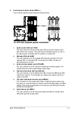
14. Chassis Intrusion (2-pin INTRUSION1)
These leads are for the intrusion detection feature for chassis with intrusion sensor or
microswitch. When you remove any chassis component, the sensor triggers and sends
a high level signal to these leads to record a chassis intrusion event. The default setting
is to short the CHASSIS# and the GND pin by a jumper cap to disable the function.
13. VGA connector (16-pin VGA_HDR1)
This connector supports the VGA High Dynamic-Range interface.
Summary of Contents for RS720-E9-RS24-E
Page 1: ...2U Rackmount Server User Guide RS720 E9 RS24 E ...
Page 10: ...x ...
Page 24: ...Chapter 1 Product Introduction 1 14 ...
Page 64: ...Chapter 2 Hardware Information 2 40 ...
Page 69: ...3 5 ASUS RS720 E9 RS24 E 3 3 Rail kit dimensions 589mm 43 6mm 900mm 43 6mm ...
Page 70: ...Chapter 3 Installation Options 3 6 ...
Page 72: ...Chapter 4 Motherboard Information 4 2 4 1 Motherboard layout ...
Page 96: ...Chapter 4 Motherboard Information 4 26 ...
Page 140: ...5 44 Chapter 5 BIOS Setup ...
Page 158: ...6 18 Chapter 6 RAID Configuration ...
Page 180: ...A 8 Appendix ...