


Chapter 1: Product Introduction
1-6
1.4
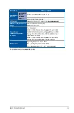
Front panel features
The barebone server displays a simple yet stylish front panel with easily accessible features.
The power and reset buttons, LED indicators, and two USB ports are located on the front
panel.
Refer to section
1.7 LED information
for the LED descriptions.
1.5
Rear panel features
The rear panel includes the expansion slots, system power sockets, and rear fans. The
middle part includes the I/O shield with openings for the rear panel connectors on the
motherboard.
Redundant power supply
Power connector
VGA port
Mgmt LAN port*
Gigabit LAN port 2
Q-Code LED
USB 3.0 ports
Power button
Gigabit LAN port 1
Expansion card back plate
•
* This port is for ASUS ASMB9-iKVM only.
•
The Q-Code LED provides the most probable cause of an error code as a starting
point for troubleshooting. The actual cause may vary from case to case.
•
Refer to the Q-Code table for details.
USB 2.0 ports
24 x 2.5” Drive Bays
handle
Front panel LEDs & buttons
handle
Asset tag
Summary of Contents for RS720-E9-RS24-E
Page 1: ...2U Rackmount Server User Guide RS720 E9 RS24 E ...
Page 10: ...x ...
Page 24: ...Chapter 1 Product Introduction 1 14 ...
Page 64: ...Chapter 2 Hardware Information 2 40 ...
Page 69: ...3 5 ASUS RS720 E9 RS24 E 3 3 Rail kit dimensions 589mm 43 6mm 900mm 43 6mm ...
Page 70: ...Chapter 3 Installation Options 3 6 ...
Page 72: ...Chapter 4 Motherboard Information 4 2 4 1 Motherboard layout ...
Page 96: ...Chapter 4 Motherboard Information 4 26 ...
Page 140: ...5 44 Chapter 5 BIOS Setup ...
Page 158: ...6 18 Chapter 6 RAID Configuration ...
Page 180: ...A 8 Appendix ...