


Chapter 4: Motherboard Information
4-18
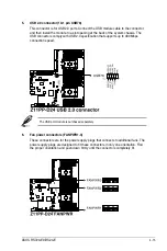
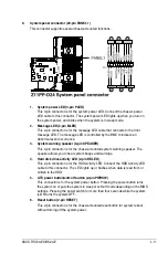
10. Auxiliary panel connector (20-2 pin AUX_PANEL1, 20-pin AUX_PANEL2)
This connector is for additional front panel features including front panel SMB, locator
LED and switch, chassis intrusion, and LAN LEDs.
1. Front panel SMB (6-1 pin FPSMB)
These leads connect the front panel SMBus cable.
2. LAN activity LED (2-pin LAN1_LED, LAN2_LED)
These leads are for the Gigabit LAN activity LEDs on the front panel.
3. Locator LED (2-pin LOCATORLED1, 2-pin LOCATORLED2)
These leads are for the locator LED1 and LED2 on the front panel. Connect the
Locator LED cables to these 2-pin connector. The LEDs will light up when the
Locator button is pressed.
4. Locator Button/Switch (2-pin LOCATORBTN)
These leads are for the locator button on the front panel. This button queries the
state of the system locator.
5. LAN activity LED and USB port (2-pin LAN3_LED, LAN4_LED, USB ports)
These leads are for the Gigabit LAN activity LEDs and USB ports on the front
panel.
Summary of Contents for RS720-E9-RS24-E
Page 1: ...2U Rackmount Server User Guide RS720 E9 RS24 E ...
Page 10: ...x ...
Page 24: ...Chapter 1 Product Introduction 1 14 ...
Page 64: ...Chapter 2 Hardware Information 2 40 ...
Page 69: ...3 5 ASUS RS720 E9 RS24 E 3 3 Rail kit dimensions 589mm 43 6mm 900mm 43 6mm ...
Page 70: ...Chapter 3 Installation Options 3 6 ...
Page 72: ...Chapter 4 Motherboard Information 4 2 4 1 Motherboard layout ...
Page 96: ...Chapter 4 Motherboard Information 4 26 ...
Page 140: ...5 44 Chapter 5 BIOS Setup ...
Page 158: ...6 18 Chapter 6 RAID Configuration ...
Page 180: ...A 8 Appendix ...