


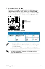

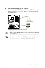


8. Thermal sensor cable connectors (2-pin OPT_TEMP1/2/3)
These connectors are for temperature monitoring. Connect the thermal
sensor cables to these connectors and place the other ends to the devices
which you want to monitor temperature. The optional fan1/2/3 can work with
the temperature sensors for a better cooling effect.
Enable
OPT FAN1/2/3 overheat protection
in BIOS if you connect thermal
sensor cables to these connectors. Refer to page 3-36 for details.
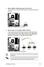
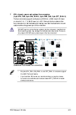
9. Chassis intrusion connector (4-1 pin CHASSIS)
This connector is for a chassis-mounted intrusion detection sensor or switch.
Connect one end of the chassis intrusion sensor or switch cable to this
connector. The chassis intrusion sensor or switch sends a high-level signal to
this connector when a chassis component is removed or replaced. The signal
is then generated as a chassis intrusion event.
By default, the pin labeled “Chassis Signal” and “Ground” are shorted with
a jumper cap. Remove the jumper caps only when you intend to use the
chassis intrusion detection feature.
2-36
Chapter 2: Hardware information
Summary of Contents for Rampage II Extreme
Page 1: ...Motherboard Rampage II Extreme ...
Page 26: ...1 10 Chapter 1 Product Introduction ...
Page 80: ...2 52 Chapter 2 Hardware information ...
Page 190: ...5 12 Chapter 5 Multiple GPU technology support ...
Page 191: ...A Appendix Debug code table The Appendix lists the debug code table for the LCD Poster ...
Page 192: ...ROG Rampage II Extreme Chapter summary A Debug code table A 1 ...
Page 196: ...A 4 Appendix Debug code table ...


