


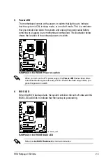

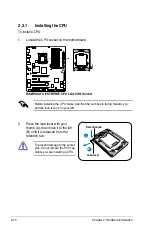


3. Lift the load lever in the direction of
the arrow to a 135º angle.
4. Lift the load plate with your thumb
and forefinger to a 100º angle.
Load plate
4
3
The CPU fits in only one correct
orientation. DO NOT force the
CPU into the socket to prevent
bending the connectors on the
socket and damaging the CPU!
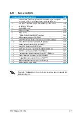
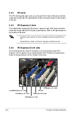
6. Position the CPU over the socket,
making sure that the gold triangle
is on the bottom-left corner of the
socket, and then fit the socket
alignment key into the CPU notch.
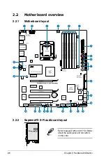
5. Remove the PnP cap from the CPU
socket.
PnP cap
Gold
triangle
mark
Alignment key
CPU notch
ROG Rampage II Extreme
2-11
Summary of Contents for Rampage II Extreme
Page 1: ...Motherboard Rampage II Extreme ...
Page 26: ...1 10 Chapter 1 Product Introduction ...
Page 80: ...2 52 Chapter 2 Hardware information ...
Page 190: ...5 12 Chapter 5 Multiple GPU technology support ...
Page 191: ...A Appendix Debug code table The Appendix lists the debug code table for the LCD Poster ...
Page 192: ...ROG Rampage II Extreme Chapter summary A Debug code table A 1 ...
Page 196: ...A 4 Appendix Debug code table ...


