


ASUS ESC8000 G4 Series
4-19
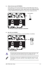
13. Chassis Intrusion (2-pin INTRUSION1)
These leads are for the intrusion detection feature for chassis with intrusion sensor or
microswitch. When you remove any chassis component, the sensor triggers and sends
a high level signal to these leads to record a chassis intrusion event. The default setting
is to short the CHASSIS# and the GND pin by a jumper cap to disable the function.
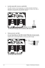
14. Micro SD card slot (MSD1)
Your motherboard supports SD Memory Card v2.00 (SDHC) / v3.00 (SDXC).
Some memory cards may not be compatible with your motherboard. Ensure that you use
only compatible memory cards to prevent loss of data, damage to your device, or memory
card, or both.
Disconnect all power (including redundant PSUs) from the existing system before you add
or remove a Memory Card, then reboot the system to access the Memory Card.
Summary of Contents for ESC8000 G4 Series
Page 1: ...4U Rackmount Server ESC8000 G4 Series User Guide ...
Page 22: ...Chapter 1 Product Introduction 1 12 ...
Page 69: ...3 7 ASUS ESC8000 G4 Series 1 2 3 4 5 6 7 8 1 2 3 ESC8000 G4 Series Front View ...
Page 74: ...4 2 Chapter 4 Motherboard Information 4 1 Z11PG D24 Series Motherboard layout ...
Page 98: ...4 26 Chapter 4 Motherboard Information ...
Page 164: ...6 18 Chapter 6 RAID Configuration ...
Page 180: ...2 Appendix ESC8000 G4 block diagram Single Root ESC8000 G4 block diagram Dual Root ...