


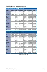


Chapter 2: Hardware Setup
2-24
5.
Remove the two (2) screws on the
ASUS PIKE II card (A), then remove the
card bracket (B).
Card bracket
6.
Secure the ASUS PIKE II card to the
ASUS PIKE II card bracket with the two
(2) screws that you removed earlier.
ASUS PIKE II card bracket
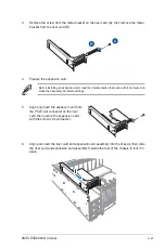
7.
Connect the mini-SAS HD cables to the ASUS PIKE II card (A), insert the ASUS PIKE
II card and the ASUS PIKE II card bracket into the PCI-E slot on the motherboard (B),
then secure it with the two (2) screws that you removed earlier (C).
Connect to ASUS
PIKE II card slot 1
Connect to ASUS
PIKE II card slot 2
Summary of Contents for ESC8000 G4 Series
Page 1: ...4U Rackmount Server ESC8000 G4 Series User Guide ...
Page 22: ...Chapter 1 Product Introduction 1 12 ...
Page 69: ...3 7 ASUS ESC8000 G4 Series 1 2 3 4 5 6 7 8 1 2 3 ESC8000 G4 Series Front View ...
Page 74: ...4 2 Chapter 4 Motherboard Information 4 1 Z11PG D24 Series Motherboard layout ...
Page 98: ...4 26 Chapter 4 Motherboard Information ...
Page 164: ...6 18 Chapter 6 RAID Configuration ...
Page 180: ...2 Appendix ESC8000 G4 block diagram Single Root ESC8000 G4 block diagram Dual Root ...