


ASUS ESC8000 G4
4-15
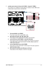
7.
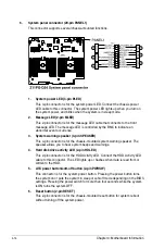
Auxiliary panel connector (20-2 pin AUX_PANEL1, 20-pin AUX_PANEL2)
This connector is for additional front panel features including front panel SMB, locator
LED and switch, chassis intrusion, and LAN LEDs.
1. Front panel SMB (6-1 pin FPSMB)
These leads connect the front panel SMBus cable.
2. LAN activity LED (2-pin LAN1_LED, LAN2_LED)
These leads are for the Gigabit LAN activity LEDs on the front panel.
3. Locator LED (2-pin LOCATORLED1, 2-pin LOCATORLED2)
These leads are for the locator LED1 and LED2 on the front panel. Connect the
Locator LED cables to these 2-pin connector. The LEDs will light up when the
Locator button is pressed.
4. Locator Button/Switch (2-pin LOCATORBTN)
These leads are for the locator button on the front panel. This button queries the
state of the system locator.
5. LAN activity LED and USB port (USB power and OC pin)
These leads are for the USB ports on the front or rear panel.
Summary of Contents for 90SF00H1-M00080
Page 1: ...4U Rackmount Server ESC8000 G4 User Guide ...
Page 63: ...3 7 ASUS ESC8000 G4 1 2 3 4 5 6 7 8 1 2 3 ESC8000 G4 Front View ...
Page 68: ...4 2 Chapter 4 Motherboard Information 4 1 Z11PG D24 Motherboard layout ...
Page 160: ...6 18 Chapter 6 RAID Configuration ...
Page 176: ...2 Appendix Z11PG D24 block diagram Single Root Z11PG D24 block diagram Dual Root ...