


ASUS ESC8000 G4
4-3
Layout contents
Internal connectors / Sockets / Jumpers / LEDs
Page
1.
PCIE SKU board power connector (4-pin PWR_CON2)
4-17
2.
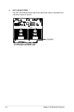
Clear RTC RAM (3-pin CLRTC1)
4-4
3.
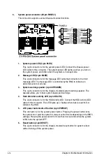
System fan connectors (4-pin SYS_FAN1-6; 4-pin CPU_FRNTFAN1-2;
6-pin GPU_FAN1-10)
4-13
4.
Mini-SAS HD connector (ISATA1-2; REARIO1)
4-11
5.
PCIE flex connectors (SLMPCIE1-2; SLMPCIE5-6; SLMPCIE9-10;
SLMPCIE17-18; SLMPCIE21-22; SLMPCIE23)
4-11
6.
TPM connector (20-1 pin TPM1)
4-12
7.
OCUUSB connector (OCUUSB1)
4-21
8.
Baseboard Management Controller setting (3-pin BMC_EN1)
4-6
9.
DDR4 thermal event setting (3-pin DIMMTRIP1-2)
4-7
10.
DMLAN setting (3-pin DM_IP_SEL1)
4-8
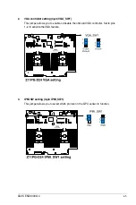
11.
VGA controller setting (3-pin VGA_SW1)
4-5
12.
VGA connector (16-pin VGA_HDR1)
4-23
13.
Rear LAN panel power connector (4-pin LAN_PWR1)
4-18
14.
Dedicated Management LAN port for iKVM (DM_LAN1)
4-25
15.
System panel connector (20-pin PANEL1)
4-14
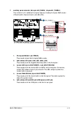
16.
Auxiliary panel connector (20-2 pin AUX_PANEL1,
20-pin AUX_PANEL2)
4-15
17.
SSI power connectors (24-pin PWR1-2)
4-16
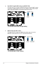
18.
Power Supply SMBus connector (12-1 pin PSUSMB1)
4-23
19.
Smart Ride Through (SmaRT) setting (3-pin SMART_PSU1)
4-8
20.
Chassis Intrusion (2-pin INTRUSION1)
4-19
21.
OCUPCIE connectors (OCUPCIE13-14)
4-22
22.
OCULAN connectors (OCULAN1)
4-22
23.
CPU socket
2-6
24.
DDR4 DIMM sockets
2-8
25.
Backplane power connectors (8-pin BPPWR1)
4-17
26.
VPP_I2C1 connector (10-1 pin VPP_I2C1)
4-21
27.
Serial port connector (10-1 pin COM1)
4-24
28.
OMNIP connector (24-pin OMNIP1-2)
4-20
29.
Hard disk activity LED connector (4-pin HDLED1)
4-12
30.
PCIE expansion slot (PCIE11)
4-26
31.
M.2 board power connector (4-pin PWR_M2)
4-18
32.
VROC_KEY connector (4-pin VROC_KEY)
4-20
33.
System Management Bus (SMBUS) connector (5-1 pin SMBUS1)
4-24
34.
IPMI SW setting (3-pin IPMI_SW1)
4-5
35.
ME firmware force recovery setting (3-pin ME_RCVR1)
4-6
36.
PCH_MFG1 setting (3-pin PCH_MFG1)
4-7
37.
Micro SD card slot (MSD1)
4-19
Summary of Contents for 90SF00H1-M00080
Page 1: ...4U Rackmount Server ESC8000 G4 User Guide ...
Page 63: ...3 7 ASUS ESC8000 G4 1 2 3 4 5 6 7 8 1 2 3 ESC8000 G4 Front View ...
Page 68: ...4 2 Chapter 4 Motherboard Information 4 1 Z11PG D24 Motherboard layout ...
Page 160: ...6 18 Chapter 6 RAID Configuration ...
Page 176: ...2 Appendix Z11PG D24 block diagram Single Root Z11PG D24 block diagram Dual Root ...