


Chapter 2: Hardware Setup
2-36
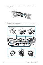
GPU card power cable
6-pin GPU card
power connector
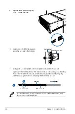
7.
Attach the other end of the power cable (6-pin power connector) to an available 6-pin
power connector on the middle of the server system (A), align and insert the golden
fingers of the GPU card into the PCIE slot on the PCIE SKU board (B), then secure the
GPU card with the two (2) screws that you removed earlier in step 1 (C).
8.
Repeat steps 1-7 if you need to install additional GPU cards.
Summary of Contents for 90SF00H1-M00080
Page 1: ...4U Rackmount Server ESC8000 G4 User Guide ...
Page 63: ...3 7 ASUS ESC8000 G4 1 2 3 4 5 6 7 8 1 2 3 ESC8000 G4 Front View ...
Page 68: ...4 2 Chapter 4 Motherboard Information 4 1 Z11PG D24 Motherboard layout ...
Page 160: ...6 18 Chapter 6 RAID Configuration ...
Page 176: ...2 Appendix Z11PG D24 block diagram Single Root Z11PG D24 block diagram Dual Root ...