ASTRO U 144 Operating Manual Download Page 53

page 53

“Alarm severities” menu

Oerating manual U 144 - 

Version 08-2016A

“Alarm severities” menu

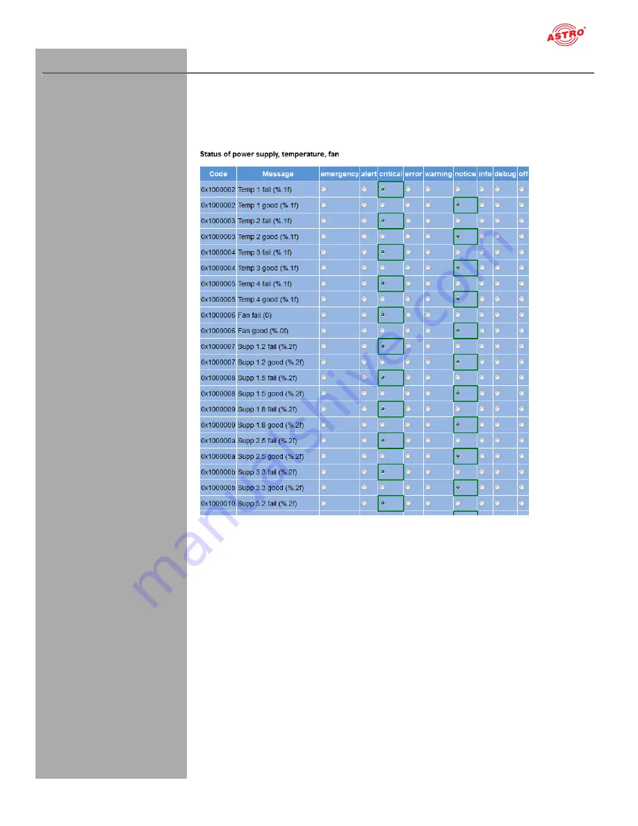
You can change the alarm settings for diverse parameters or deactivate the alarm display for a param-
eter, when preferred. To do so, click on the item “Alarm Severities” in the menu at the left. A set of tables 
for different parameter groups then appears: 

Figure 60: Alarm Severities

The preset options for the alarm messages are identified by a green frame. Retaining these settings is 
recommended.

Summary of Contents for U 144

Page 1: ...Version 08 2016A ...

Page 2: ...settings menu page 28 SAT RX menu page 30 Service Filter menu Seite 31 RX 1 1 RX 1 4 menu page 33 CAM Mux menu page 35 CAM 1 CAM 4 menu page 36 IP TX menu page 39 TX 1 8 MPTS menu Seite 40 TX 9 SPTS menu Seite 42 User settings menu page 43 SSL settings menu page 45 Licensing menu page 48 Update config menu page 49 System log menu page 52 Alarm severities menu page 54 Active alarms menu page 55 Sta...

Page 3: ...ecycling symbol indicates components or packaging materials which can be recycled cardboard inserts plastic film and bags Used batteries must be disposed of at approved recycling points Batteries must be completely discharged before being disposed of This symbol indicates components which must not be disposed of with household rubbish Copyright information Parts of the software used with this prod...

Page 4: ...th power plugs before opening the device To avoid any potential risks to the greatest extent possible it is very important that you observe the safety instructions in the operating manual for the U100 230 U 100 48 base unit Assembly instructions IMPORTANT The outputs of the signal converter must not be operated without connecting a combining network or terminating impedance The module U 144 may on...

Page 5: ...is completely recyclable Electronic devices must not be disposed of with household waste but rather according to DIRECTIVE 2002 96 EC OF THE EUROPEAN PARLIAMENT AND OF THE COUNCIL from January 27 2003 on waste electrical and electronic equipment must be properly disposed of When it is no longer in use please bring the device for disposal to one of the public collection points for this purpose ASTR...

Page 6: ...ransmitters or be fed back to one of the other CAM modules Optionally the output signals from the DVB S2 receiver can also be routed directly to one of the IP transmitters The two Ethernet data ports in the U 144 can then be used to output up to 8 IP video data streams To use the devices properly read the following safety and operating instructions attentively The U 144 plug in module features the...

Page 7: ...e relevant EC directives and adhere to the requirements specified therein Figure 1 top U 144 installed in the U 100 base unit fitted with three plug in modules Figure 1 middle U 144 front panel 1 Screw for the front panel 2 Display for management IP addresses data IP addresses status messages etc 3 Status display 4 Control and data knob menu switch Figure I bottom U 194 front panel after removal 5...

Page 8: ...f the plug in module software currently installed is displayed Active alarms The current error messages are displayed DVB S2 module 1 The status of the four channels set is displayed CAM modules 1 4 The respective reception channel forwarded to the CAM module is displayed The different text colours refer to Red Error the corresponding display in the web interface log book is error Yellow Warning t...

Page 9: ...o establish a mechanical connection between the signal converter and the base unit Both the mains HF connections and the network connections are connected to this backplane There is usually a temperature controlled fan for cooling the signal converter on the backplane This can be replaced while the device is operating To ensure the position of the backplane and therefore the position of the respec...

Page 10: ...e unit To do so proceed as follows Figure 3 Installing the backplane in the base unit TASK 1 When the U 100 base unit is in its delivery state the three installation slots for the backplanes are covered by dummy plates see figure 3 above Start by removing the Phillips head screws 1 and 2 from the dummy plate at the required installation position left middle or right and remove the dummy plate 2 Yo...

Page 11: ...w and remove the front panel together with the display The four CI slots and the release buttons for ejecting the CI modules are visible Start by pushing each CI card into a CI module and then push each module into one of the four CI slots in the U 194 To remove a CI module press the corresponding eject button and remove the module 1 Screw for the front panel 5 Release button CI slot 3 6 Release b...

Page 12: ...or laptop must be in the same sub network as the U 144 The sub network mask of the U 144 is set to 255 255 255 0 upon delivery The PC or laptop which is connected must therefore be assigned an IP address 192 168 1 x You can now start the configuration using the web browser user interface General information on the structure of the web browser interface The configuration interface is divided into t...

Page 13: ...displayed the device is oper ational If the circle is red then a fault has occurred A list of current errors is available under the menu item Active alarms NOTE For reasons of security you should change the access data valid upon delivery user name and password to prevent unauthorised access The procedure is described in the section Changing user data Changing the IP address NOTE If you wish to ch...

Page 14: ...ls for the reception channel using a drop down menu in the web user interface The signals from the four reception channels are forwarded via a multiplexer CAM Mux to CAM modules 1 to 4 the overview shows as an example the signal from reception channel 1 to CAM 1 and the signal from reception channel 3 to CAM 2 see the red line connecting them The signals from the reception channels are forwarded v...

Page 15: ...8 2016A Figure 8 The signal flow in the U 144 IP TX 1 2 3 4 5 6 7 8 TX Mux Data A Ethernet Ethernet Data B Testgenerator CAM 1 CAM 2 CAM 3 CAM 4 DVB S2 RX 1 1 1 2 1 3 1 4 CAM Mux Testgenerator RF 2 RF 1 F jack F jack 4 x Input switch via software dropdown list RF 4 RF 3 F jack F jack ...

Page 16: ... the Satellite drop down menu Select the required polarisation level from the drop down menu in the Polarisation Band column Select a supply voltage for the LNB from the Voltage drop down menu If you wish to use a 22 kHz pulse control activate the radio button on in the 22 kHz Tone column To save your changes click on the Submit button below the table Now click on the Transponder item in the main ...

Page 17: ... in the menu at the left You will now see the following overview Figure 10 Displaying the transponder status The message OK should now appear in the Status line in the Transponder 1 1 Settings table Now check the most important parameters in the table which follows Channel Status Ensure that you check the values in the Quality Tuner Level and C N lines here ...

Page 18: ...bmit button below the table More information on signal routing can be found in the section Configuring signal paths using the switch matrix Now click on the item CAM 1 in the menu at the left You may have to press the refresh button in your browser several times to update the page You will now see the following table Figure 12 CAM settings A list of the individual services which the module CAM 1 i...

Page 19: ...Submit button below the table Configuring the IP transmitter To complete the process you should now configure and activate the IP transmitter To do so click on the item IP TX 1 in the web browser interface menu You will now see the following table Figure 14 Configuring the IP transmitter Enter the IP address and port of a reception device e g for one of the signal converters from the U 1xx series ...

Page 20: ...ng value should appear in the line Total transmit frames generated from IP TX 1 in the Ethernet frames table More information about the values in the Statistics overview can be found in the section Statistics menu Once you have successfully completed all the steps described then the most important settings re quired to decrypt a data stream have been entered in the device To ensure error statuses ...

Page 21: ... settings for the U 144 displayed click on the Status item in the menu at the left You can now see the overview shown in figure 18 Figure 16 Status display The following tables are displayed Ethernet status Configuration data and status of the Ethernet port Figure 17 Status display Ethernet ...

Page 22: ... IP address configurable Mode Ethernet mode display value Transmit Data transmission rate display value Receive Data reception rate display value Status display of the IP transmitters Figure 19 Status display IP TX channels The values set for the following parameters are displayed in the table IP TX Settings for the four IP transmitters for port A and B respectively TX IP socket Destination IP add...

Page 23: ... are displayed in the Miscellaneous table Temperature Temperature display in C for the mainboard as well as DVB S2 1 4 and 5 8 Supply 1 2 V 1 2 V supply voltage Supply 1 8 V 1 8 V supply voltage Supply 2 5 V 2 5 V supply voltage Supply 3 3 V 3 3 V supply voltage Supply 5 2 V 5 2 V supply voltage Supply 13 V 13 V supply voltage mainboard only Fan Fan rotation speed Supply 1 0 V 1 0 V supply voltage...

Page 24: ...nual U 144 Version 08 2016A page 24 Memory status Figure 21 Status display System resources Information on the internal resources of the operating system can be viewed in the System resources table No settings can be made here ...

Page 25: ... parameters are displayed and can be configured MAC MAC address of the respective interface Active Activate the radio button on to activate the interface Activate the radio button off to deactivate the interface Mode Connection type identified automatically Address IP address Subnet Netmask Broadcast Broadcast address calculated Gateway Gateway IP if available otherwise set this to 0 0 0 0 NOTE Wh...

Page 26: ...s are displayed and can be configured Base Address Enter an address for the base unit being used here If the U 168 is managed using the U 100 C controller and several U 100 base units are being used then each base unit must be allocated an address of its own This setting only has to be entered for one module per base unit Slot Address In accordance with the coding of the backplane of the U 144 per...

Page 27: ... clicking on the Load 2nd button you can query this status again How to save the configuration onto the local computer or FTP server is explained in the section Software update and configuration files When you click the Force Save button all settings are saved immediately The time settings for auto matically saving changes are then overridden Click on the Default button if you wish to restore the ...

Page 28: ...cal polarisation this is used when the Voltage parameter in the Input Settings table is set to auto Voltage Horizontal Select the LNB voltage for horizontal polarisation this is used when the Voltage parameter in the Input Settings table is set to auto DiSEqC If you are using a reception unit with a DiSEqC controller activate the corresponding radio button for the version supported here If no DiSE...

Page 29: ... Submit button below the last table to save your changes Click on Reset form to restore the original settings Satellite settings You can enter settings for selecting the satellite used for reception in the Input Settings table Figure 28 Satellite DiSEqC Settings table You can enter DiSEqC settings for the individual satellites here You can select the following parame ters individually using the re...

Page 30: ...four reception channels in the Transponder Settings ta ble Figure 29 Transponder Settings table Select the preferred transponder from the drop down menu in the Transponder Freq Input TS ID ON ID column The items in the list are grouped according to the satellites selected in the Input Settings table If you change the activation or deactivation status of inputs or outputs in one of the two tables t...

Page 31: ...te is too low some of the services may not be transmitted properly If PIDs without referencing are desired to be deleted from the transport stream click on the radio button drop or choose pass if these PIDs are desired to remain in the transport stream In row Filter Type you can choose if the services selected in the next table Service Selection are being deleted from the transport stream radio bu...

Page 32: ...an simply add all services to the list click button Add All or delete all selected services at once click button Remove All Click the Reset Form button to restore the original settings In the next table Status you can see an overview of all services with their curent status drop or pass Figure 32 Table Status ...

Page 33: ...te or deactivate the channel select the corresponding radio button Transponder Select the preferred reception system from the drop down menu Manual Settings Select the preferred reception frequency from the drop down menu If you select the item manual from the list you can enter the required value in kHz in the manual freq input field Frequency Transponder frequency Symbol Rate Transponder symbol ...

Page 34: ... S or DVB S2 Tuned IF Frequency intermediate frequency in kHz TS ID ON ID transport stream ID original network ID Demod Power demodulation in dBm Input Power input sensitivity in µV C N signal noise ratio in dB C N Margin limitation of signal noise ratio in dB BER Bit Error Rate Symbol Rate symbol rate BER Bit Error Rate Puncture Rate puncturing rate Modulation modulation process Rolloff rolloff S...

Page 35: ...reception channel to one of the CAM modules by clicking on the corresponding radio button Furthermore the output signal from each CAM module can be forwarded on to one of the other CAM modules If no input signal is available you can also forward the signal from the test generator see Test gener ator section to the respective CAM modules The transport stream ID the network ID and the alias name for...

Page 36: ...erature too high and voltage error Figure 32 CAM module information Click on the symbol in the left column to have an overview of the CA systems displayed If you click on the Menu button in the right column the MM menu for the module opens Entering decryption settings The second table allows you to add the service for decryption and if preferred to limit the decryption to individual elements Figur...

Page 37: ...stream PID Enter the required PID in the respective input field manually for the Secondary and Tertiary fields see the section RP PX menu The Content option allows selection according to the content of the elementary streams A drop down menu with the following options appears in the Value s column Video All video elementary streams are decrypted Audio All audio elementary streams are decrypted Tel...

Page 38: ...ervices marked in bold type include at least one encrypted service Click on the symbol in the left column to have the detailed settings for decryption displayed Figure 36 Status details display The advanced view shows all the settings made in the Decryption Settings table decrypted PIDs type selected content language Furthermore it shows whether the content is encrypted or unen crypted scrambled o...

Page 39: ... the SPTS list To add channels type in the desired number of channels into the input field Number in row Add SPTS Channels and click on the plus symbol in column Action To delete a range of existing channels type in the desired channels in row Remove SPTS Channels in X Y manner e g 10 14 or the like Then click on the minus symbol in column Action NOTE Up to 504 SPTS channels can be used NOTE It is...

Page 40: ...e original settings To configure one of the 8 MPTS channels click on one of the items TX1 TX 2 TX 3 TX 8 in the left column You will then see the following table Figure 39 Table 1 IP TX1 Channel Settings You can activate or deactivate forwarding of the selected IP output to ports A and B respectively by clicking on the corresponding radio button The MAC address is displayed for ports A and B respe...

Page 41: ... the protocol by clicking the corresponding radio button FEC Forward error correction Select the number of columns from the first drop down menu off or a value between 1 and 20 Select the number of rows from the second drop down menu off or a value between 4 and 20 Select one of the two options Columns and rows Col Rows and Column only Col only from the third drop down menu Select one of the optio...

Page 42: ...table to save the changes Click on Reset form to restore the original settings To configure an SPTS channel in detail click on one of the items TX9 TX 10 TX 11 TX 24 in the left column You will now see the following table Figure 42 Table 1 IP TX Channel Settings Here you can activate or deactivate the routing of the selected IP output to ports A and B by clicking on the corresponding radiobutton F...

Page 43: ...assword must contain at least 5 characters You can increase the minimum requirements for passwords using the Enforced Password Policy option see below To delete a user account activate the corresponding checkbox Delete for the respective account in the right column of the table The following settings can also be entered Timeout You can enter a time for the automatic logout in minutes in this input...

Page 44: ... Users who have been configured on the device will be deactivated when a RADIUS server is configured The RADIUS server must be configured accordingly Users with the service type Administra tive are the device administrators When you click the checkbox Enable Radius login the RADIUS function is activated if the RADIUS server is able to be reached If this is not the case the RADIUS function remains ...

Page 45: ...SSL settings table In the following table Generate a CSR for this device individual items of information about the device can be entered Certificate Signing Request address organisation etc Figure 47 Generate a CSR for this device table By clicking the Download CSR button you can create a Certificate Signing Request with which your CA can issue a certificate for the device The input field Private ...

Page 46: ...ificate button Delete an existing device certificate click the Clear certificate button Regenerate a device key and device certificate click the Regenerate button The device administers two keys pairs of certificates generated and user The following figure shows which certificate and which key are used Figure 49 Using the certificates keys yes yes yes User has deposited certificate User key exists...

Page 47: ...tem in the menu at the left The following input mask now appears Figure 50 Enabling licences using the licence key Now enter the licence key sent to you in the input field The key or keys can be entered in the input mask using Copy Paste Then click on the Submit button to transmit the text to the device If the licence is valid this is confirmed with the message License is valid An error message is...

Page 48: ...ser interface menu The Software update table then appears in the content area at the top Figure 51 Firmware update Now click on the Search button and select the path to the memory location of the update archive downloaded beforehand Then click on the Update and Reboot button to start the update process Please wait for the process to be completed and for the device to reboot Available Update Archiv...

Page 49: ...ply click on the corresponding file link to download the file Loading saving firmware and configurations using T FTP You can update firmware using a T FTP server using the table Firmware update and configuration via server and load or save configuration files Figure 55 Loading saving firmware updates and configurations using T FTP To carry out the preferred action start by selecting an action from...

Page 50: ... specified update archive on the SD memory card is unpacked and programmed into the module enter the version number Overwrite backup firmware action The device software is saved in two partitions The soft ware saved in the first partition is used for operating the module while the second partition is used to keep a backup copy ready for the event that the update process fails As long as both parti...

Page 51: ...og You can check or configure the following parameters individually System log settings Figure 57 Filter settings for the system log display You can activate or deactivate filters for displaying the log entries here To have messages from the corresponding category displayed activate the checkbox allocated to the category NOTE You can connect to higher level management systems using the Syslog and ...

Page 52: ...ess of de leting the old log entries is listed as the first entry specified the user account and the current time upon deletion You can also download the following logfiles System log CSV format Debug log CSV format NOTE You can also download a complete archive of log files plus the complete device configuration by clicking on the link To retrieve an archive of SUPPORT FILES click here You will ne...

Page 53: ...rameters or deactivate the alarm display for a param eter when preferred To do so click on the item Alarm Severities in the menu at the left A set of tables for different parameter groups then appears Figure 60 Alarm Severities The preset options for the alarm messages are identified by a green frame Retaining these settings is recommended ...

Page 54: ...g item in the menu at the left The following table now appears Figure 61 Active alarm table The table provides information about error messages currently active The Message column shows the error message in plain text NOTE You can also access the Active Alarm Table by clicking the red point in the status line in the upper section of the user interface ...

Page 55: ...nd reception receive are specified for the respective interfaces Management A Management B Data A and Data B Ethernet frames Figure 63 Ethernet frames The following parameters are displayed for the interfaces Data A and Data B in this order The number of IP frames transmitted to the processor is specified in the first three lines of the table Number of defective frames Number of frames which could...

Page 56: ...on 08 2016A page 56 Ethernet TX Figure 64 Ethernet TX In reference to forward error correction the smallest number of free FEC buffers measured at all is dis played in the first line The total number of FEC buffers is displayed in the second line ...

Page 57: ... interface statistic properties which are displayed are for information purposes only and are used to describe the network They could be useful for customer service in the event of a fault Devices menu To have an overview of the local data memory in the device displayed click on the item Devices in the menu at the left Among other things the total memory capacity the capacity of the unused memory ...

Page 58: ...0950 1 You must disconnect the power plug before opening the device Service tasks The following tasks which involve the removal of screw connections can be performed by appropri ately instructed service personnel Removal and installation of signal converters e g U 144 and power modules even when the U 100 is operating Replacing power modules After removing the screws from the cover of the power mo...

Page 59: ...F jack Reflection loss dB 10 Input symbol rate MS s max 45 0 depends on DVB S2 Modulation DVB S Roll off factors 0 20 0 25 0 35 DVB S LDPC 1 2 1 3 2 3 2 5 3 5 4 5 5 6 8 9 9 10 depends on DVB S2 Modulation Viterbi decoding according DVB standard 1 2 2 3 3 4 5 6 7 8 automatically manually DiSEqC Control CI interfaces CI slots 4 x front access Supported modules excerpt others on request Alphacrypt As...

Page 60: ...r in full without prior agreement of the ASTRO company These operating instructions have been written by ASTRO Strobel Kommunikationssysteme GmbH Olefant 1 3 D 51427 Bergisch Gladbach Bensberg Tel 02204 405 0 Fax 02204 405 10 eMail kontakt astro kom de Internet www astro kom de All the information contained in this document has been checked in good faith The ASTRO company cannot be held liable for...

Reviews: