


42
●
Calibration and guiding should always be done at 1x guide rate.
●
Turn all backlash to zero (Keypad and computer software) and turn off "stiction."
●
Since the Mach2GTO has absolute encoders, PE correction is no longer needed. The encoder eliminates all
periodic error, so no need for doing PE compensation. Autoguiding works superbly well with the encoder mounts.
●
With an encoder mount like the Mach2GTO as well as the 1100GTO or 1600GTO mounts with absolute encoders,
you want to have a delay between guide pulses. The reason is that it takes a moment for the axis to fully respond
and reverse in Dec when a command comes in. In an encoder mount, each command will be fully accommodated by
the encoder loop, whereas in a non-encoder mount it may take several move commands for the axis to finally fully
reverse. If you start sending the same move command in an encoder mount without waiting for the first one to finish,
you will definitely overshoot.
A 2 - 3 second delay between commands is a good recommendation. There is no periodic error that you need to
chase in RA and the Dec axis isn't going anywhere. This assumes that you don't have very poor polar alignment that
causes the axes to drift at high rates.
MaxIm DL
™
Guiding Recommendations
●
In MaxIm DL
™, you want to use "Telescope" for guiding. However, you first have to connect to the mount via your
USB cable,. Click on the little Observatory Dome icon to bring up the Setup window. Press the Telescope Connect
button. This will then allow the program to send direct move commands which are more accurate than the Pulse
Guide commands.
●
For setting the guide delays in MaxIm DL
™
, bring up the Guider Settings - Advanced window. Set the "Delay After
Corrections" to 2 seconds or 3 seconds. You can also set your Min Move and Max Move in that window.
PHD2 Guiding Recommendations
●
Set a delay of 2 to 3 seconds between guide exposures. No need to chase gear errors because there aren't any.
●
Use whatever exposure time you want to get a good signal/noise ratio (usually from 1 to 5 seconds).
●
Use Guiding Assistant to gauge the seeing and set your MinMove to what is recommended. It will tell you all the
vital information about how your mount is reacting
●
Depending on seeing, the aggressiveness can be set between 50% to 90%.
●
Be sure that your guide scope focal length is set properly in PHD2 in the scope setup window.
●
Each time that you change the guide scope or set up new you first must perform a calibration run in PHD2.
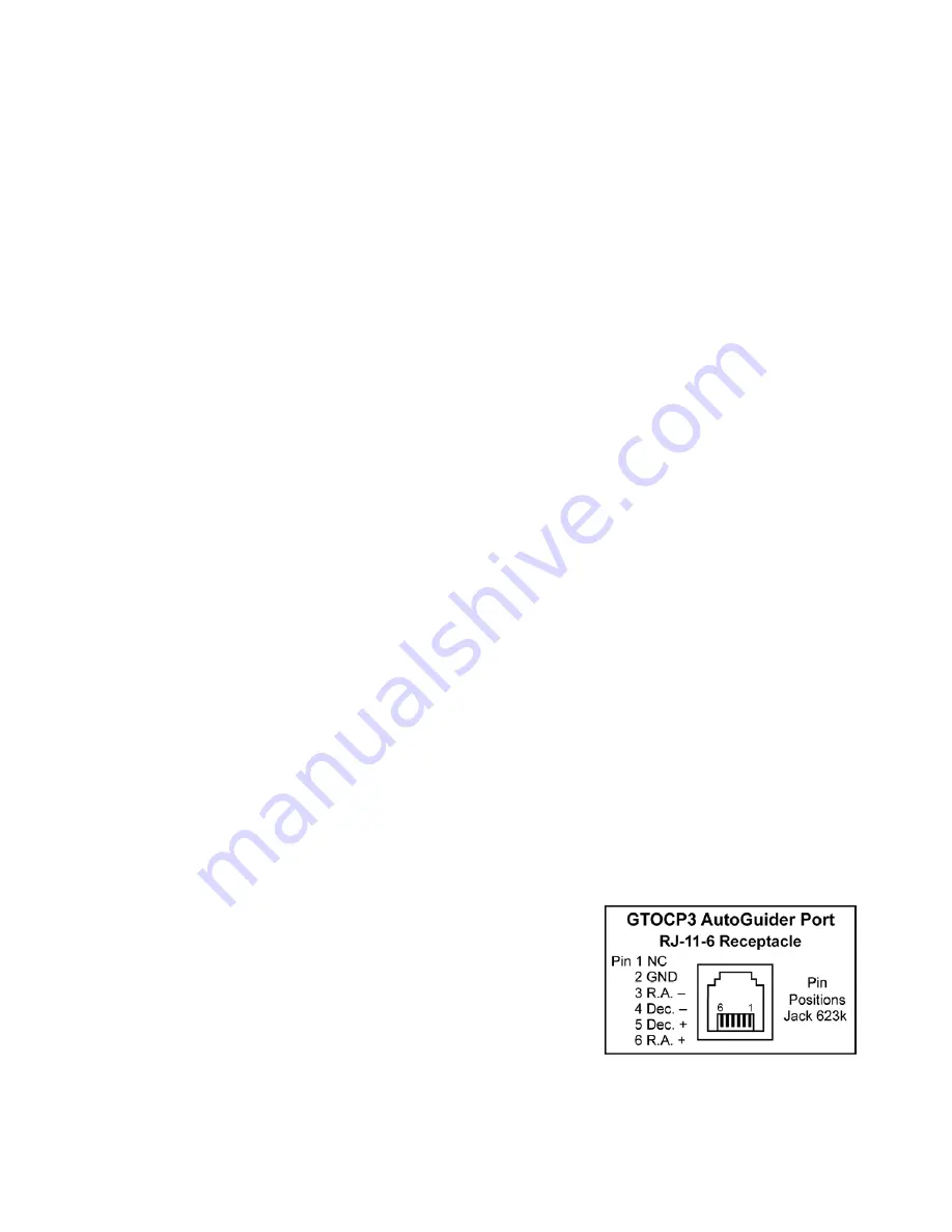
How to Test an Autoguider Port
Here is the test for the autoguider port. To perform the test, you will need a foot or so of 6 conductor flat phone cable
with a standard RJ11-6 plug on the end. Remove the insulating material from 3 – 4 inches of the bare end of the cable to
expose the six colored wires. Remove the insulation from about 1/4” to 3/8” of the ends of each of these wires, although
you could skip the wire corresponding to pin #1 if you wish. The #1 wire will typically be either the white or the blue,
depending on how the plug was attached. In addition to the cable just described, you'll find a short test lead with alligator
clips on each end to be very handy.
Note the pinout diagram.
You may find it helpful to list the wire numbers and color codes before you start.
Most likely, you will have: blue, yellow, green, red, black & white or else the
exact reverse of this. If you hold the test cable so that you are looking at the
bottom of the plug with the plug’s clip away from you, you can see the colored
wires in order exactly as they go into the jack illustrated here.
To test:
1. Power up the mount.
2. Remove the covers from the gearboxes that cover the reduction spur gears.
3. If you have never done so before, set the keypad button rate to 1x and press the direction buttons to familiarize your-


